Internal combustion engine with variable valve gear

a variable valve gear, combustion engine technology, applied in the direction of valve arrangement, yielding coupling, coupling, etc., can solve the problems of difficult to significantly mitigate pumping loss by greatly prolonging the valve-open period, and the phase change mechanism of the vane-type cam cannot easily produce great phase differences, so as to improve fuel efficiency, reduce the effect of pumping loss and reducing the effect of valve opening period

Active Publication Date: 2012-08-07
MITSUBISHI MOTORS CORP
View PDF11 Cites 23 Cited by
  • Summary
  • Abstract
  • Description
  • Claims
  • Application Information

AI Technical Summary

Benefits of technology

[0007]The object of the present invention is to provide an internal combustion engine with a variable valve gear, capable of delaying the closing timings of intake valves without failing to make a valve train compact and of extending the valve-open period, thereby greatly mitigating pumping loss.
[0009]Thus, the valve-open period can be extended by making the variable-phase angular range of the second cam phase change mechanism, that is, phase differences between the respective opening and closing timings of the first and second intake valves, wider than that of the first cam phase change mechanism. By performing the delay angle control and valve-open period increasing control in, for example, low-load, low-speed operation, therefore, pumping loss can be considerably mitigated to greatly improve the fuel efficiency. Further, in-cylinder flow can be enhanced by increasing the phase differences between the respective opening and closing timings of the first and second intake valves. Thus, combustion stability can be improved even with mitigated pumping loss and at a low actual compression ratio with a small amount of air, and the fuel efficiency can be further improved. Since mixing between air and fuel is also enhanced, moreover, emission of unburned components in exhaust gas can be reduced.

Problems solved by technology

Due to structural restrictions, however, these vane-type cam phase change mechanisms cannot easily produce great phase differences.
Accordingly, the opening and closing timings of the intake valves cannot be substantially changed, so that it is difficult to considerably mitigate pumping loss by greatly extending the valve-open period.

Method used


Image

  • Internal combustion engine with variable valve gear
  • Internal combustion engine with variable valve gear
  • Internal combustion engine with variable valve gear

Examples


Embodiment Construction

[0019]One embodiment of the present invention will now be described with reference to the accompanying drawings.

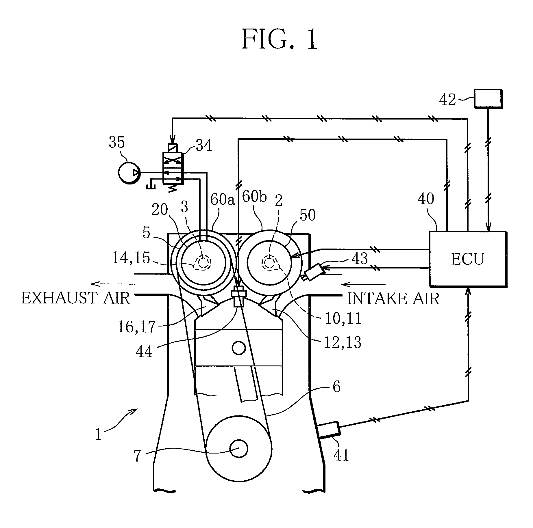
[0020]FIG. 1 is a schematic structure diagram of an internal combustion engine (engine 1) with a variable valve gear according to the present embodiment.

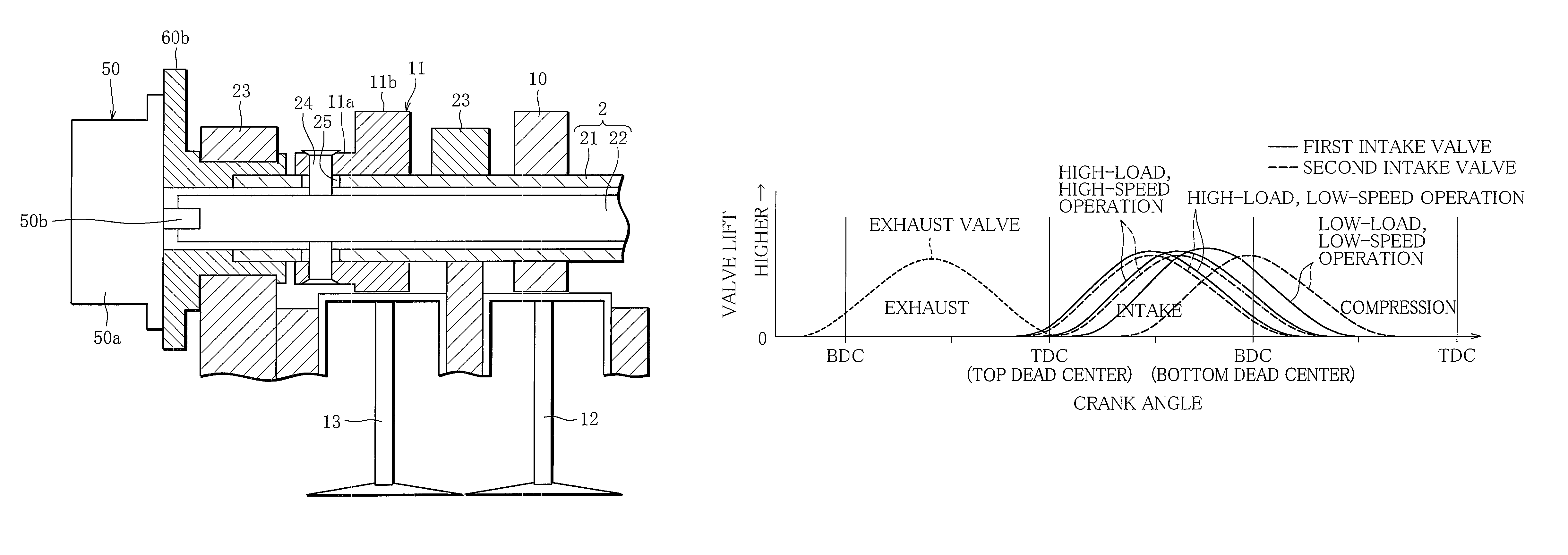
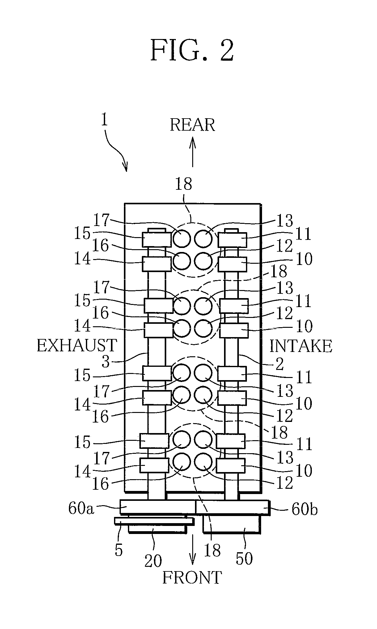
[0021]As shown in FIG. 1, the engine 1 of the present embodiment comprises a DOHC valve train. A cam sprocket 5 is connected to the front end of an exhaust camshaft 3 of the engine 1. The cam sprocket 5 is coupled to a crankshaft 7 by a chain 6. Further, the exhaust camshaft 3 and an intake camshaft 2 are coupled to each other through gears 60a and 60b. As the crankshaft 7 rotates, therefore, the exhaust camshaft 3 is rotated together with the cam sprocket 5, while the intake camshaft 2 is rotated by the gears 60a and 60b. Intake valves 12 and 13 are opened and closed by intake cams 10 and 11 on the intake camshaft 2, and exhaust valves 16 and 17 by exhaust cams 14 and 15 on the exhaust camshaft 3.

[0022]FIG. 2 is a schemat...


PUM


Abstract

Each cylinder is provided with a first intake valve and a second intake valve, and a first intake cam for driving the first intake valve and a second intake cam for driving the second intake valve are coaxially pivotally supported on an intake camshaft. A first cam phase change mechanism which varies respective phases of the first and second intake cams relative to a crankshaft of the internal combustion engine is combined with a second cam phase change mechanism which varies a phase of the second intake cam relative to the first intake cam. The second cam phase change mechanism is set to have a variable-phase angular range wider than that of the first cam phase change mechanism.

Description

BACKGROUND OF THE INVENTION[0001]1. Field of the Invention[0002]The present invention relates to an internal combustion engine with a cam phase change mechanism capable of changing the phase of an intake cam.[0003]2. Description of the Related Art[0004]Conventionally, there are internal combustion engines that comprise a cam phase change mechanism as a variable valve gear, which changes the phase of an intake cam to vary the opening and closing timings of an intake valve. Further, a technique has been developed in which the cam phase change mechanism is applied to internal combustion engines that are provided with a plurality of intake valves for each cylinder. According to this technique, the opening and closing timings of only some of the intake valves are varied in accordance with the engine load and speed.[0005]In one such internal combustion engine, the opening and closing timings of the specific intake valves are delayed by the cam phase change mechanism, based on the operatin...

Claims


Application Information

Patent Timeline
Patent Type & Authority Patents(United States)
IPC IPC(8): F01L1/34
CPCF01L1/047F01L1/053F01L1/26F01L1/3442F01L1/34F01L2800/06F01L2001/0473F01L2001/34493
Inventor MURATA, SHINICHI
Owner MITSUBISHI MOTORS CORP
Why Eureka
Try Eureka