Manipulator and control method therefor

a manipulator and control method technology, applied in the field of manipulators, can solve the problems of easy occurrence of unnecessary movement at the other axes, large collapsing interference torque, and operator's sense of uneasiness, and achieve the effect of high degree of freedom

Active Publication Date: 2012-08-07
KARL STORZ GMBH & CO KG
View PDF15 Cites 809 Cited by
  • Summary
  • Abstract
  • Description
  • Claims
  • Application Information

AI Technical Summary

Benefits of technology

[0010]It is one object of the present invention to provide a manipulator and control method therefor, in which a high level of freedom can be attained, yet wherein even if torque is applied with respect to one axis, the device can be controlled such that unnecessary movements do not occur at the other axes.

Problems solved by technology

In particular, in the case that the tip of the end effector grips a needle or a living body organism (hereinafter referred to also as a workpiece), or when shearing or the like is carried out, comparatively large torques are required, such that the collaterally generated interference torque becomes large, and unnecessary movement generated at the other axes easily arises.
It is thought that such movements may also lead to cases where some sense of uneasiness is felt by the operator.

Method used


Image

  • Manipulator and control method therefor
  • Manipulator and control method therefor
  • Manipulator and control method therefor

Examples


first embodiment

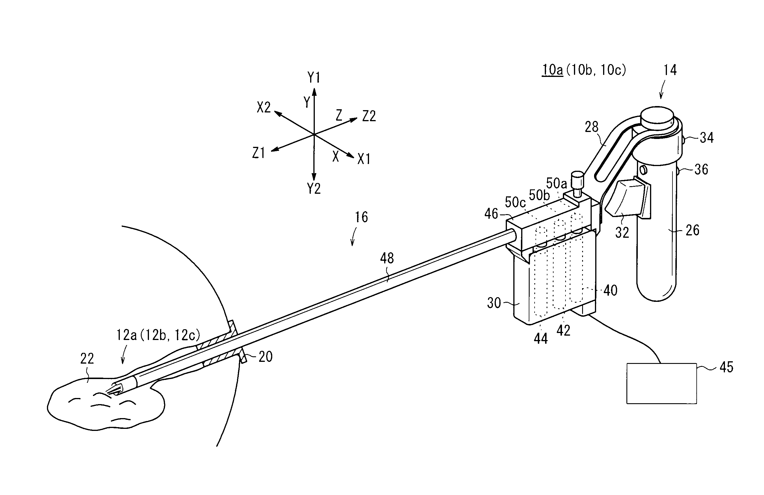
[0138]In this manner, in accordance with the manipulator 10a and control method therefor of the first embodiment, by means of the controller 45, the torque detector section 504 detects the timing at which the gripper axis torque τg′ is generated, and based on an excess amount Δβ that defines the detection signal, and taking as a standard the angles θ1, θ2 at the current positions the posture axes, a correction of the command signal in the same direction as the directions of the interference torques τ1, τ2 is carried out. Owing thereto, with the manipulator 10a, the appropriate three degrees of freedom can be attained when performing laparoscopic surgery, and even if elongation or warping of the wires 52, 54 occurs due to generation of the torque τg′ on the gripper axis, almost no unnecessary motion takes place on the other axes.

[0139]Accordingly, surgery can be performed without the operator experiencing any sense of uneasiness. Further, as a result of compensating the elongation on...

second embodiment

[0142]Next, a manipulator lob shall be described. When describing the manipulator 10b (as well as the later-mentioned manipulator 10c), elements thereof which are the same as those of the manipulator 10a shall be designated using the same reference characters, and detailed descriptions of such features shall be omitted.

[0143]As shown in FIGS. 15 to 18, at the working unit 12b of the manipulator 10b, the gear body 126, the gear body 300, the main axis member 128 and the gear body 130, are axially supported in succession with respect to the shaft 112, from the Y1 direction toward the Y2 direction.

[0144]On the gear body 126, the portion thereof corresponding to the region 132a (see FIG. 5) is set thinly in profile.

[0145]In place of the aforementioned tubular member 140, a thin protective plate 171 is provided on the main axis member 128. The protective plate 171 is equipped with a central hole 171b therein through which the shaft 112 is inserted. The protective plate 171 has a roughly...

third embodiment

[0180]Next, a manipulator 10c shall be described.

[0181]As shown in FIGS. 23 to 26, at the working unit 12c of the manipulator 10c, the gear body 126, the gear body 300, and the main axis member 360 (second drive rotor) 360 are axially supported in succession with respect to the shaft 112, from the Y1 direction toward the Y2 direction.

[0182]The main axis member 360 is an element corresponding to the aforementioned main axis member 128, and in the same manner as the manipulator 10a discussed above, the main axis member 360 is driven through the wire 52 by the motor 40. In the main axis member 360, the axial portion thereof projects somewhat in the Y2 direction (see FIG. 26), and the wire 52 is wound around the axial portion.

[0183]The gear body 300 is driven by the motor 42 through the wire 54. Further, the gear body 130 of the manipulator 10b is not provided. In other structural aspects, the manipulator 10c is the same as the aforementioned manipulator 10b.

[0184]The basic structure ...


PUM


Abstract

A manipulator has a working unit including an end effector and a posture axis for changing the orientation of the manipulator, a compound mechanism provided on the working unit, and a controller for actuating a gripper axis, a yaw axis, and a roll axis by respectively controlling movement positions of three motors. The controller includes a torque generation detector for detecting a timing at which torque is generated on the gripper axis. When the controller detects the timing at which a torque τg′ is generated on the gripper axis under operation of a given motor, the movement positions of the plural motors are shifted and set, corresponding to the directions at which interference torques are generated with respect to the yaw axis and the roll axis, and to predetermined positions of the same directions.

Description

BACKGROUND OF THE INVENTION[0001]1. Field of the Invention[0002]The present invention relates to a manipulator having an operating section including an end effector axis and one or more posture axes by which the orientation of the end effector axis is changed, together with a control method therefor. In particular, the present invention relates to a manipulator equipped with a compound mechanism for operating the end effector axis and the posture axes thereof, and to a control method for such a manipulator.[0003]2. Description of the Related Art[0004]In laparoscopic surgery, a number of small holes are opened in a patient's abdomen or the like, and an endoscope, a manipulator (or forceps), or the like is inserted, and surgery is carried out while the surgeon observes an image from the endoscope on a monitor. In this type of laparoscopic surgery, owing to the fact that opening of the abdominal cavity is unnecessary, the burden on the patient is small, and number of days required for ...

Claims


Application Information

Patent Timeline
Patent Type & Authority Patents(United States)
IPC IPC(8): G05B11/01
CPCA61B19/22B25J9/1641A61B2017/2943A61B2019/2249G05B2219/39457Y10T74/20G05B2219/41361G05B2219/45118Y10T74/20207Y10T74/20305G05B2219/41195A61B34/70A61B34/72
Inventor JINNO, MAKOTOSUNAOSHI, TAKAMITSUOMORI, SHIGERU
Owner KARL STORZ GMBH & CO KG
Why Eureka
Try Eureka