Laser beam analysis apparatus

a laser beam and analysis apparatus technology, applied in the direction of optical radiation measurement, semiconductor lasers, instruments, etc., can solve the problem that the structure does not perform a resonator function, and achieve the effect of avoiding the use of neutral density filters and reducing the number of optical elements

Active Publication Date: 2012-08-07
HAAS LASER TECH
View PDF12 Cites 26 Cited by
  • Summary
  • Abstract
  • Description
  • Claims
  • Application Information

AI Technical Summary

Benefits of technology

[0028]Another important objective is to minimize the number of optical elements and to avoid using neutral density filters.

Problems solved by technology

However, said structure performs no resonator function in this inventive apparatus.

Method used


Image

  • Laser beam analysis apparatus
  • Laser beam analysis apparatus
  • Laser beam analysis apparatus

Examples


Embodiment Construction

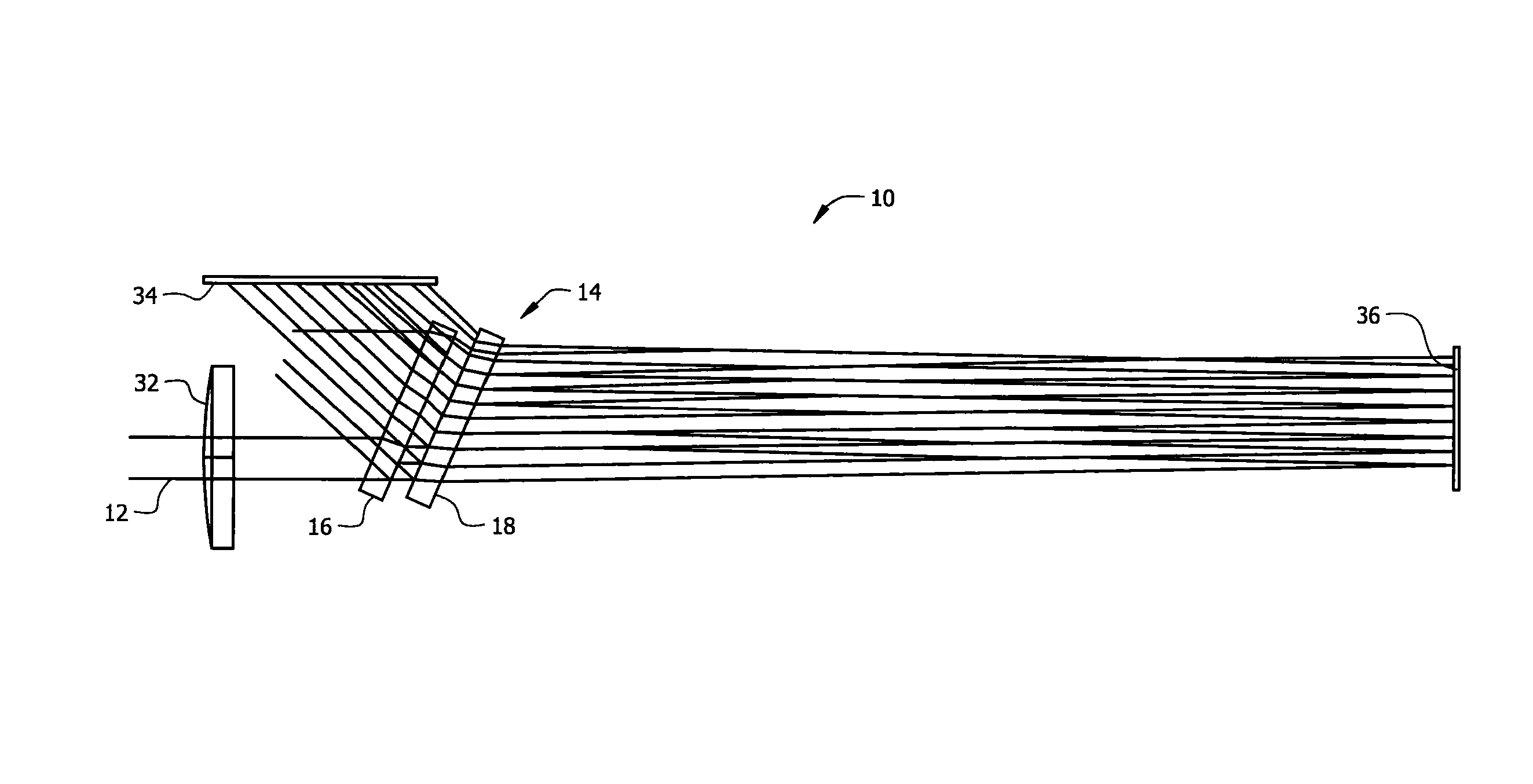
[0038]Referring now to FIG. 1, it will there be seen that a diagrammatic representation of the novel apparatus is denoted as a whole by the reference numeral 10.

[0039]Commercially available high power fiber lasers have powers exceeding ten kilowatts (10 kW). Some have powers exceeding twenty kilowatts (20 kW). The novel apparatus accepts fiber laser beam 12 with a power greater then ten kilowatts into an attenuation module that includes a pair of high reflecting mirror plates 20 and 24.

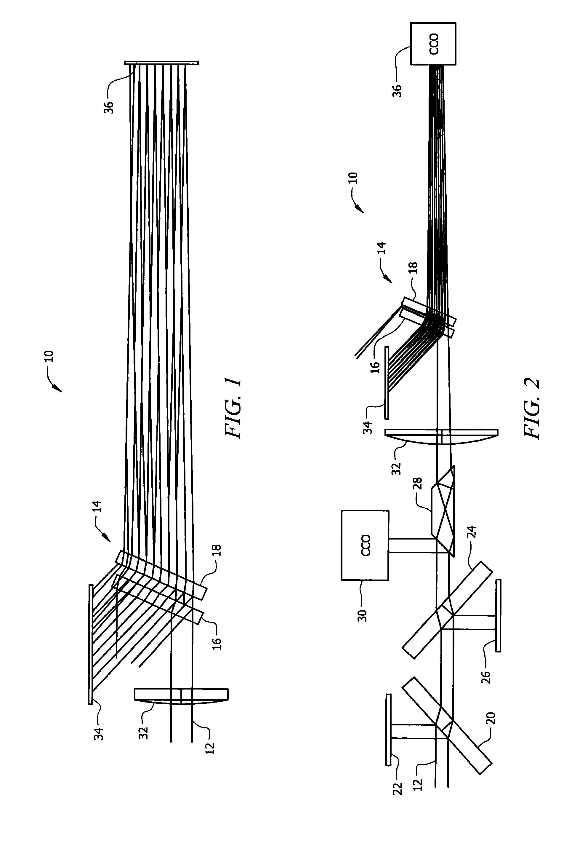
[0040]When the novel apparatus is configured for a high power laser, as depicted in FIG. 2, laser beam 12 strikes first plate 20 which is oriented at a forty five degree (45°) angle of incidence. More than ninety nine percent (99%) of the light is reflected toward a first water-cooled high power beam dump 22 to dissipate the vast majority of the laser's power.

[0041]The small amount of light that passes through the highly reflective surface of first plate 20 strikes the second surface of first mirror p...


PUM

PropertyMeasurementUnit
angleaaaaaaaaaa
angleaaaaaaaaaa
powersaaaaaaaaaa

Abstract

An apparatus that enables real time measurement of the spatial profile, circularity, centroid, astigmatism and M2 values of a laser beam generated by a high power laser beam. The apparatus employs the optics used in a process application, including a focus lens and cover glass. An attenuation module includes a pair of high reflecting mirror plates disposed in parallel, spaced apart relation to one another at a common angle of incidence to the laser beam. A beam dump is positioned out of a path of travel of the laser beam and in receiving relation to light reflected by the first and second mirrors. A camera detects spots of light that pass through the first and second mirrors. A high power attenuator formed by a highly reflective mirror pair is positioned between the source and the attenuation module. A second embodiment includes a single mirror plate having highly reflective surfaces.

Description

BACKGROUND OF THE INVENTION[0001]1. Field of the Invention[0002]This invention relates, generally, to the art of analyzing laser beams. More particularly, it relates to the art of analyzing high power laser beams.[0003]2. Description of the Prior Art[0004]A conventional apparatus for analyzing a high power laser beam includes a rotating needle that acts like a knife edge. The rotating needle reflects a small sampling of the focused laser beam into a detector. The needle, as it is rotated, moves along an optical axis and measures the beam waist of a focused laser beam.[0005]Primes GmbH sells a unit that is capable of measuring powers up to 10 kilowatts, CW. The unit requires careful alignment and takes many minutes to make a measurement. It is bulky and does not facilitate real time measurement in a production process.[0006]Multiple patents, such as U.S. Pat. Nos. 5,064,284, 5,069,527, 5,078,491, 5,100,231, 5,214,485, 5,267,012 and 5,459,565, disclose methods of analyzing a multimode...

Claims


Application Information

Patent Timeline
Patent Type & Authority Patents(United States)
IPC IPC(8): G01J1/00
CPCB23K26/426G01J1/04G01J1/0418G01J1/4257G02B27/106G02B27/108G02B27/144B23K26/705H01S3/10H01S5/0683
Inventor SCAGGS, MICHAEL J.
Owner HAAS LASER TECH
Why Eureka
Try Eureka