Polarization-sensitive infrared image sensor including a plurality of optical fibers

a polarization-sensitive, optical fiber-based technology, applied in the field of polarimeters, can solve the problems of limited success in approaches, and cannot allow polarization-sensitive imaging of dynamically-changing scenes

Active Publication Date: 2012-08-07
NAT TECH & ENG SOLUTIONS OF SANDIA LLC
View PDF9 Cites 42 Cited by
  • Summary
  • Abstract
  • Description
  • Claims
  • Application Information

AI Technical Summary

Benefits of technology

[0008]The present invention relates to a polarization-sensitive infrared image sensor which comprises a 2-D array of polarizers to receive infrared light from a scene and to filter the infrared light according to polarization. A 2-D array of optical fibers is located proximate to the 2-D array of polarizers to receive the filtered infrared light from each polarizer at an entrance end of the 2-D array of optical fibers and to transmit the filtered infrared light to an exit end of the optical fibers. A 2-D array of infrared photodetectors (also referred to herein as a focal plane array) is located proximate to the exit end of the 2-D array of optical fiber

Problems solved by technology

However, this sequential method does not allow polarization-sensitive imaging of dynamically-changing scenes due to movement

Method used


Image

  • Polarization-sensitive infrared image sensor including a plurality of optical fibers
  • Polarization-sensitive infrared image sensor including a plurality of optical fibers
  • Polarization-sensitive infrared image sensor including a plurality of optical fibers

Examples


Embodiment Construction

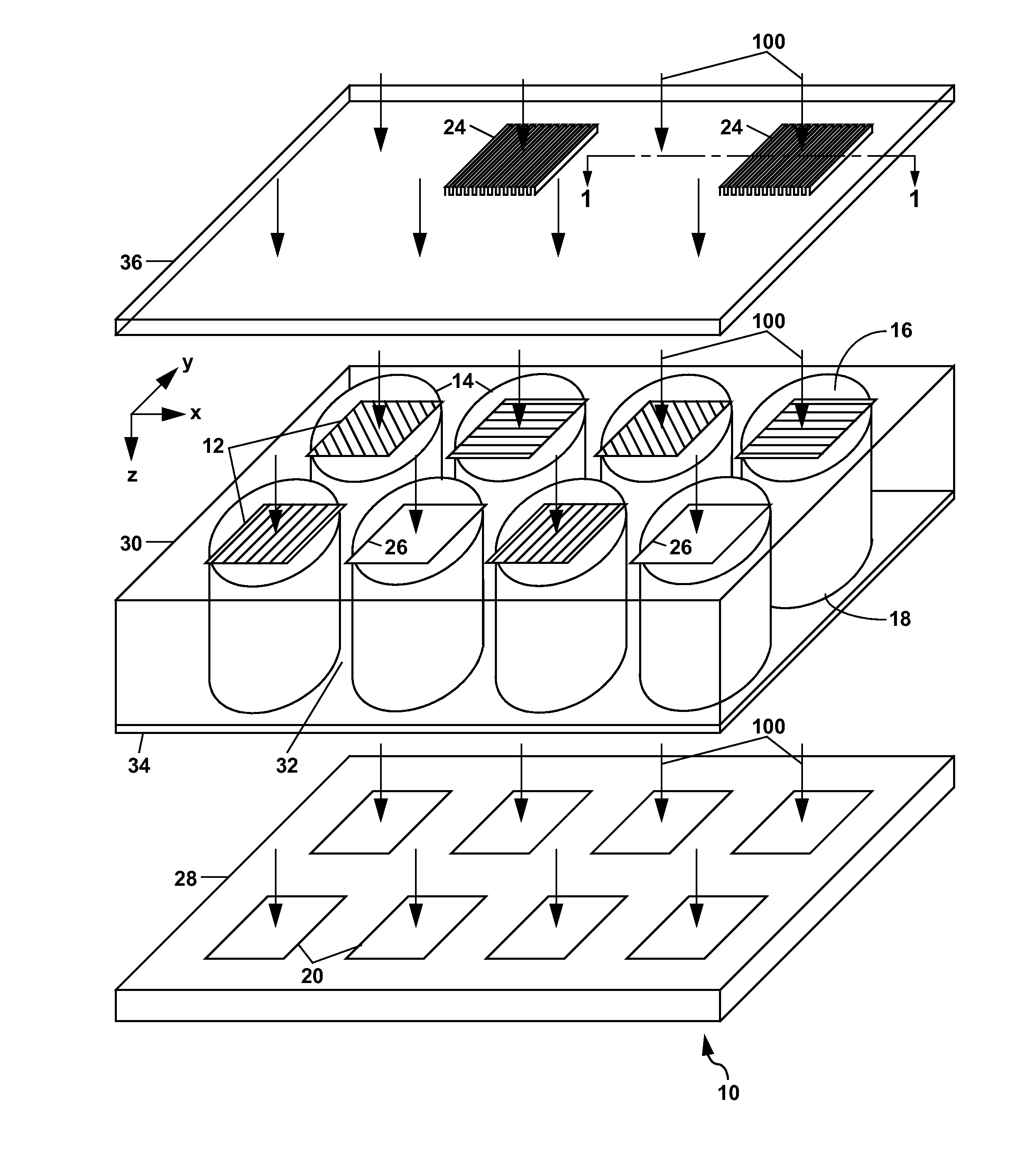
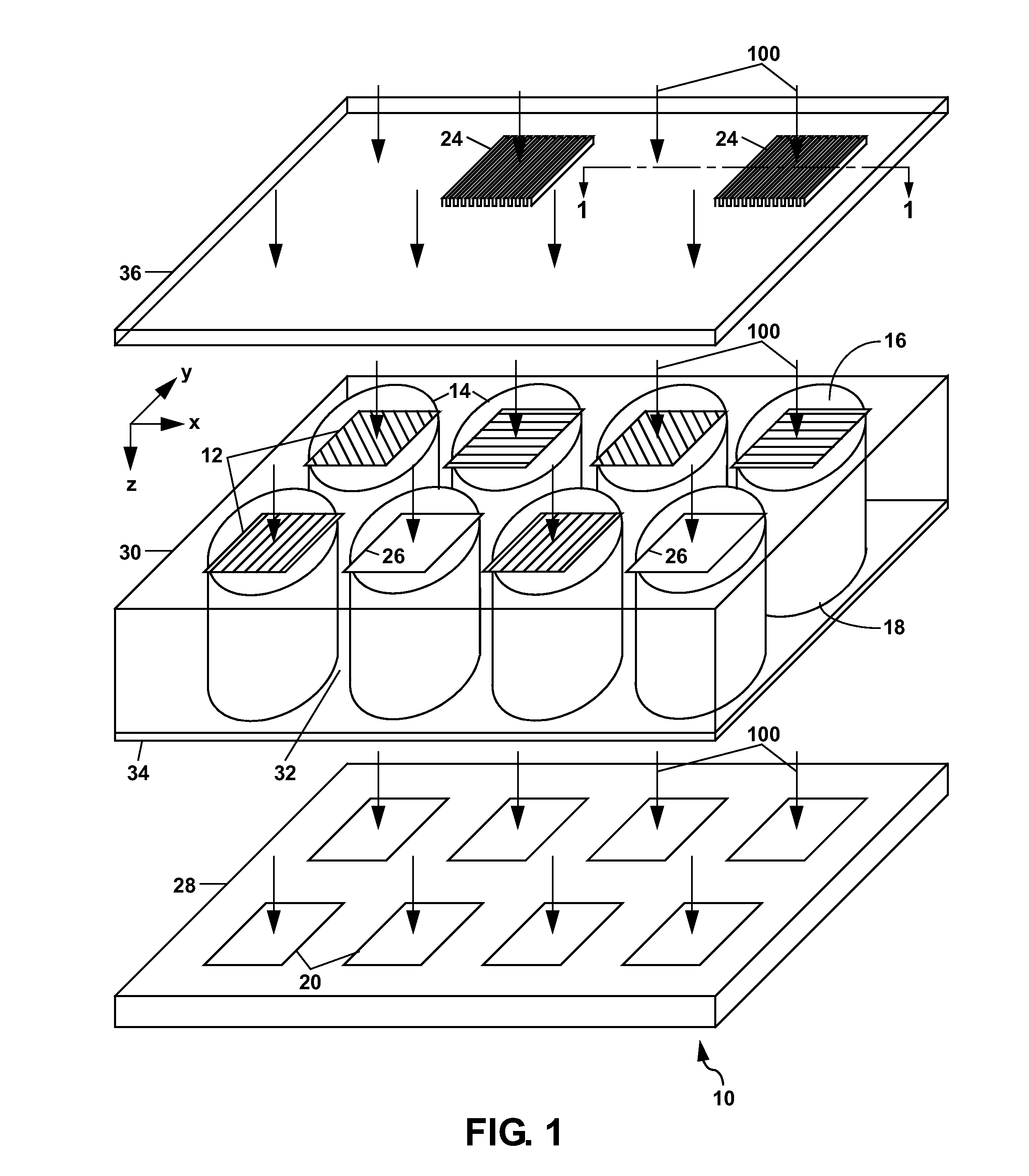
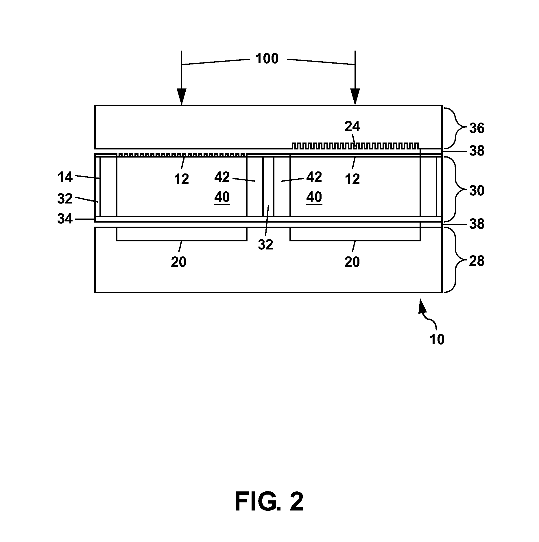
[0023]Referring to FIG. 1, there is shown an exploded perspective view of a first example of the polarization-sensitive infrared imaging sensor 10 of the present invention. The sensor 10 comprises a plurality of polarizers 12 which can be arranged in a two-dimensional (2-D) array to filter infrared light 100 received from a scene 110 (see FIG. 3) and imaged onto the 2-D array of polarizers 12. Each polarizer 12 filters the infrared light 100 according to polarization for a pixel of the infrared image of the scene 110 which is incident on that polarizer 12.

[0024]In FIG. 1, a 2-D array of optical fibers 14 is located proximate to the polarizers 12 to receive the filtered infrared light 100 from each polarizer 12 at an entrance end 16 of the optical fibers 14, with the optical fibers 14 transmitting the filtered infrared light 100 to an exit end 18 of the fibers 14. The polarizers 12 can be formed directly on the entrance end 16 of the optical fibers 14 as shown in FIG. 1.

[0025]A 2-D a...


PUM


Abstract

A polarization-sensitive infrared image sensor (also termed a snapshot polarimeter) utilizing a 2-D array of polarizers to filter infrared light from a scene according to polarization, and a 2-D array of photodetectors (i.e. a focal plane array) to detect the filtered infrared light and generate polarization information which can be used to form a polarization-sensitive image of the scene. By forming each polarizer on an optical fiber in a fiber optic faceplate, the polarizers can be located facing a 2-D array of retarders to minimize diffraction effects of the infrared light. The optical fibers also guide the filtered infrared light to the photodetectors to reduce cross-talk in the polarization information. The polarizers can be formed as wire grid polarizers; and the retarders can be formed as subwavelength surface-relief gratings.

Description

GOVERNMENT RIGHTS[0001]This invention was made with Government support under Contract No. DE-AC04-94AL85000 awarded by the U.S. Department of Energy. The Government has certain rights in the invention.FIELD OF THE INVENTION[0002]The present invention relates to imaging polarimeters, and in particular to snapshot polarimeters which simultaneously measure different polarization states of an image using infrared light.BACKGROUND OF THE INVENTION[0003]There is currently a significant level of interest in extending the capabilities of infrared imaging systems beyond conventional amplitude imaging to include polarimetry which provides additional information which can be used to highlight or suppress different materials in a scene, or objects at different orientations. Polarimetry can be useful, for example, to distinguish man-made objects in a scene from natural objects. The usual method for imaging polarimetry is to sequentially measure each polarization component of an image, and then t...

Claims


Application Information

Patent Timeline
IPC IPC(8): G02B27/28
CPCG01J4/04G01N21/21G02B5/3058G02B5/3083G02B6/08
Inventor KEMME, SHANALYN A.CRUZ-CABRERA, ALVARO A.
Owner NAT TECH & ENG SOLUTIONS OF SANDIA LLC
Why Eureka
Try Eureka