Method and system for distributing multimedia contents through a wireless communications network, particularly a mobile telephony network

a wireless communications network and multimedia content technology, applied in the field of wireless communications networks, can solve the problems of limiting the bandwidth that can be allocated for a given user, poor data exchange capabilities, and limiting the possibility of multiple users simultaneously accessing available gpr services

Active Publication Date: 2012-08-07
TELECOM ITALIA SPA
View PDF11 Cites 30 Cited by
  • Summary
  • Abstract
  • Description
  • Claims
  • Application Information

AI Technical Summary

Benefits of technology

[0029]The Applicant has found that the mobile stations in a cell that are exploiting a given multicast service, and thus would be indistinguishable for the network (because they share the same physical communication resources) can be rendered distinguishable from each other by defining a rad

Problems solved by technology

However, these second-generation cellular networks, albeit satisfactory for voice communication, offer very poor data exchange capabilities.
Similarly to the PSTNs, second-generation cellular networks are in fact switched-circuit networks; this greatly limits the bandwidth that can be allocated for a given user.
Clearly, this limits the possibility of simultaneously accessing available GPRS services by several users, unless the radio resources are overdimensioned.
Furthermore, the Applicant observes that the proposed method shows an additional and more severe drawback: the different mobile stations in a cell that are exploiting a given multicast service are indistinguishable for the network apparatuses, which are thus impossibilitated to address information to a specific mobile station.
In the Applica

Method used


Image

  • Method and system for distributing multimedia contents through a wireless communications network, particularly a mobile telephony network
  • Method and system for distributing multimedia contents through a wireless communications network, particularly a mobile telephony network
  • Method and system for distributing multimedia contents through a wireless communications network, particularly a mobile telephony network

Examples


Embodiment Construction

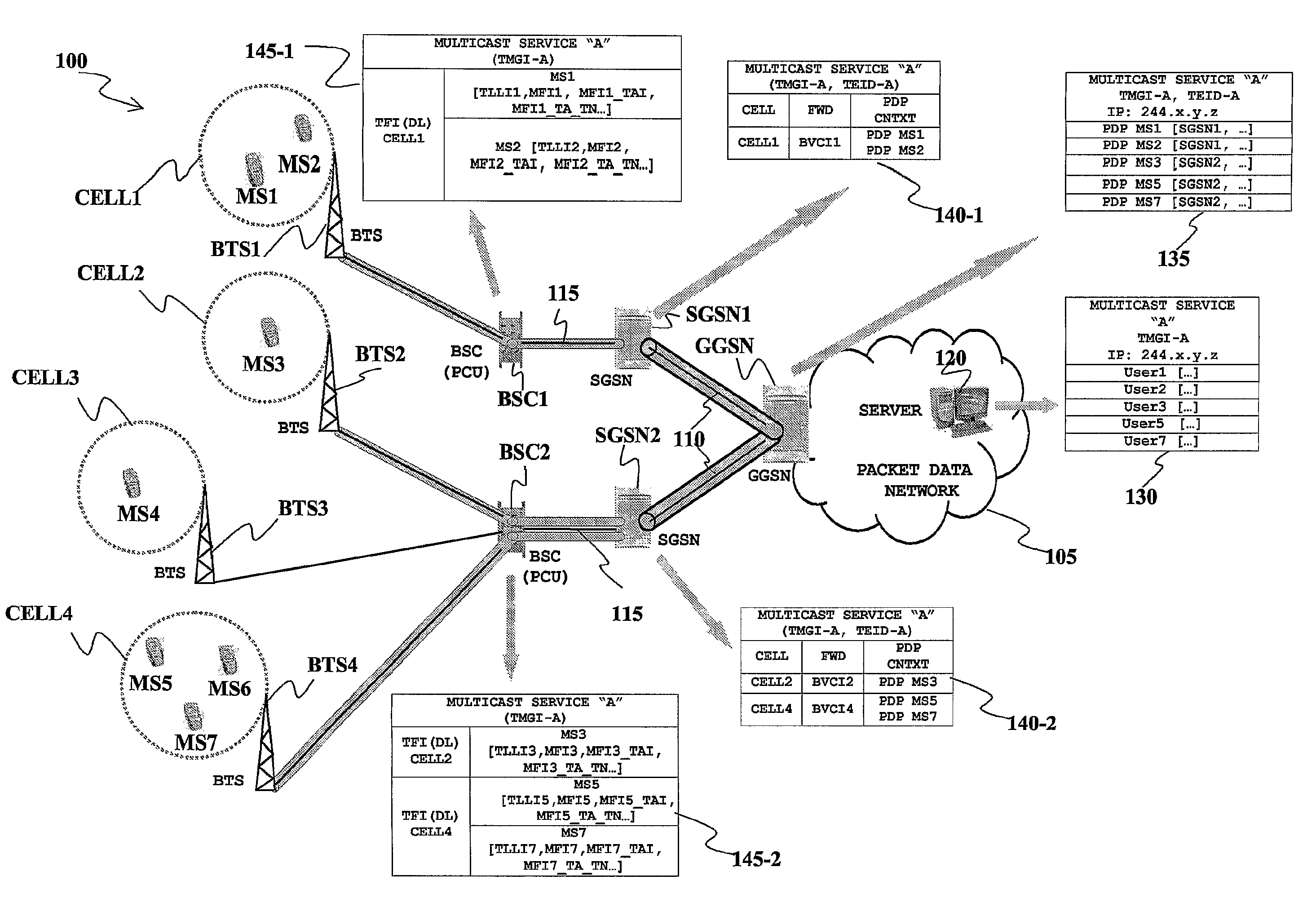
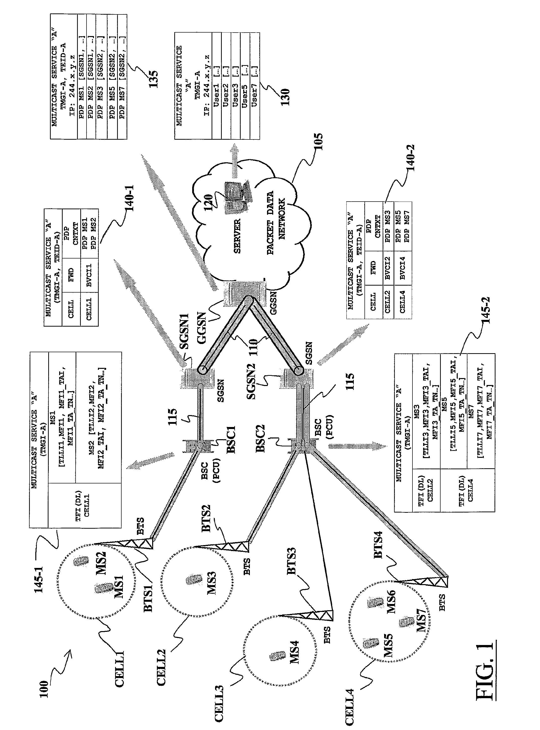
[0077]With reference to the drawings and, particularly, to FIG. 1, a cellular mobile communications network 100, particularly a GSM network, is schematically shown.

[0078]The mobile communications network 100 comprises a plurality of Base Station Subsystems (BSSs), each one providing coverage for cellular communications in a respective geographic region.

[0079]The generic BSS comprises a plurality of Base Transceiver Stations (BTSs), each one covering a respective geographic area within the region covered by the BSS; the number of BTSs in a BSS may be in the practice rather high but for simplicity of the drawing, only four BTSs BTS1, BTS2, BTS3 and BTS4 (pictorially represented by an antenna) with an associated cell CELL1, CELL2, CELL3 and CELL4 (schematically depicted as an area surrounded by a dashed circle) are shown in FIG. 1. The generic BTS communicates with users' Mobile Stations (MS), typically cellular phones, which are located in the BTS's cell, such as the MSs MS1 and MS2 w...


PUM


Abstract

In a wireless communications network having a base station subsystem controlling at least one network cell, and in which the base station subsystem communicates with mobile stations in the cell through radio blocks, a method of distributing information contents received in data packets at the base station subsystem to the mobile stations, includes obtaining, starting from the data packets, radio blocks to be transmitted through the network cell, labeling the radio blocks with a first radio link identifier, identifying a logic connection between a mobile station and the base station subsystem, communicating the first radio link identifier to a first mobile station in the network cell, and in case at least one second mobile station in the network cell, asks to receive the information contents, communicating thereto the first radio link identifier. The method further includes having the first mobile station and the at least one second mobile station assigned respective second radio link identifiers to be included in the radio blocks.

Description

CROSS REFERENCE TO RELATED APPLICATION[0001]This application is a national phase application based on PCT / EP2004 / 050517, filed Apr. 14, 2004, the content of which is incorporated herein by reference.BACKGROUND OF THE INVENTION[0002]1. Field of the Invention[0003]The present invention generally relates to the field of telecommunications, and more particularly to wireless, mobile communications networks, such as mobile telephony networks. Specifically, the invention concerns the distribution of relevant amounts of data, such as multimedia information contents, to mobile user terminals (e.g., mobile phones) through a wireless, mobile communications network.[0004]2. Description of the Related Art[0005]Mobile telephony networks were initially conceived for enabling voice communications, similarly to the wired, Public Switched Telephone Networks (PSTNs), but between mobile users.[0006]Mobile telephony networks have experienced an enormous spread, especially after the introduction of secon...

Claims


Application Information

Patent Timeline
IPC IPC(8): H04W4/00H04L45/16H04L12/18H04L12/56H04W4/06H04W28/04H04W74/00H04W76/02H04W76/11
CPCH04L12/189H04W76/021H04W28/04H04W72/005H04W76/11H04W72/30
Inventor SORBARA, DAVIDEZUCCA, ENRICOMADELLA, MARIOCATALANO, GIUSEPPE
Owner TELECOM ITALIA SPA
Why Eureka
Try Eureka