Branch and bound techniques for computation of critical timing conditions

Active Publication Date: 2012-08-14
CADENCE DESIGN SYST INC
View PDF7 Cites 11 Cited by
  • Summary
  • Abstract
  • Description
  • Claims
  • Application Information

AI Technical Summary

Benefits of technology

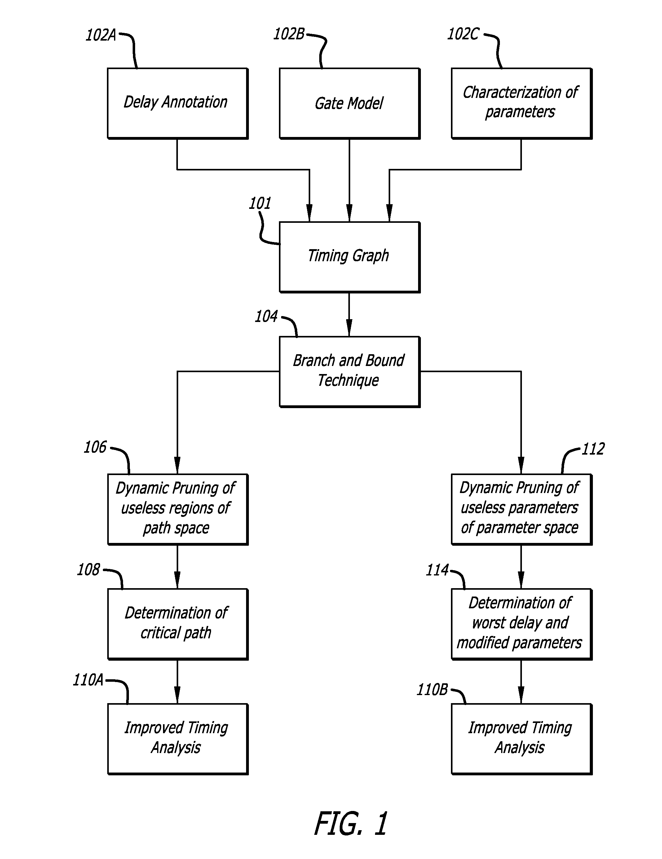
[0007]In one embodiment of the invention, a method of analyzing an electronic circuit design is disclosed including analyzing a hierarchy of a netlist of a circuit; forming a timing graph of the circuit; and in response to the timing delay of a plurality of timing delay edges, dynamically pruning paths of the plurality of paths using branch and bound techniques to reduce the path space down to one or more critical timing paths of the circuit. The hierarchy of the netlist of the circuit is analyzed to determine one or more primary inputs (PI) and one or more primary outputs (PO) of the circuit at an upper level, and one or more internal vertices of the circuit at lower levels between the one or more primary inputs (PI) and the one or more primary outputs (PO). The timing graph includes a plurality of timing delay edges representing timing delay between the one or more primary inputs (PI), the one or more internal vertices, and the one or more primary outputs (PO) to form a plurality of paths of a path space from the one or more primary inputs (PI) to the one or more primary outputs (PO). The dynamic pruning is performed on bounds of timing delay that are a function of one or more circuit parameters to reduce the path space down to the one or more critical timing paths of the circuit that have a worse case metric of timing delay between the one or more primary inputs (PI) and the one or more primary outputs (PO).
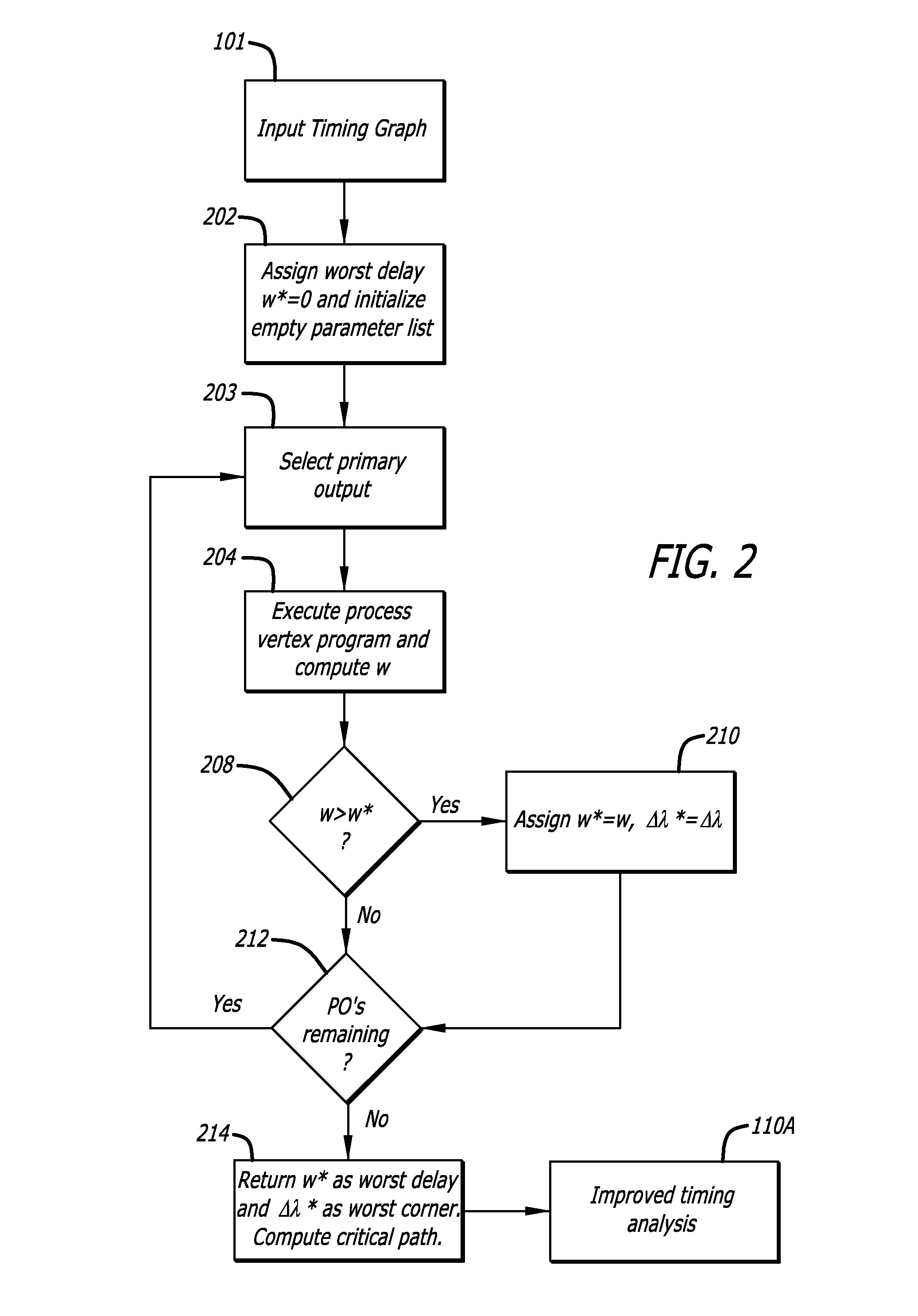
[0008]In another embodiment of the invention, an apparatus for electronic circuit design is disclosed including one or more processors to execute machine readable instructions stored in a machine readable medium to analyze a circuit design. The machine readable instructions stored in the machine readable medium include instructions to analyze a hierarchy of a netlist of a circuit to determine one or more primary inputs (PI) and a plurality of primary outputs (PO) of the circuit at an upper level, and one or more internal vertices of the circuit at lower levels between the one or more primary inputs (PI) and the plurality of primary outputs (PO); instructions to form a timing graph of the circuit including a plurality of timing delay edges representing timing delay between the one or more primary inputs (PI), the one or more internal vertices and the one or more primary outputs (PO); instructions to add a super primary output (SPO) to the timing graph of the circuit with timing delay edges having zero timing delay coupled to the plurality of primary outputs (PO) to form a plurality of paths of a path space from the one or more primary inputs (PI) to the super primary output (SPO); and instructions, responsive to the timing delay of the plurality of timing delay edges, to dynamically prune paths of the plurality of paths using branch and bound techniques on bounds of timing delay that are a function of one or more circuit parameters to reduce the path space down to one or more critical timing paths of the circuit with a worse case metric of timing delay between the one or more primary inputs (PI) and the super primary output (SPO).
[0009]In yet another embodiment of the invention, a method of analyzing an electronic circuit design is disclosed. The method of analyzing the electronic circuit design includes analyzing a hierarchy of a netlist of a sequential circuit to determine one or more primary inputs (PI) and o

Problems solved by technology

Exhaustive approaches are slow, because in most cases the size of the solution space is exponential (either in the number of paths or in the number of parameters), and th

Method used


Image

  • Branch and bound techniques for computation of critical timing conditions
  • Branch and bound techniques for computation of critical timing conditions
  • Branch and bound techniques for computation of critical timing conditions

Examples


Example

[0038]In the following detailed description of the embodiments of the invention, numerous specific details are set forth in order to provide a thorough understanding of the embodiments of the invention. However, the embodiments of the invention may be practiced without these specific details. In other instances well known methods, procedures, components, and circuits have not been described in detail so as not to unnecessarily obscure aspects of the embodiments of the invention.

Introduction

[0039]Combinatorial optimization is a branch of optimization in applied mathematics and computer science. It is related to operations research, algorithm theory and computational complexity theory that sit at the intersection of several fields, including artificial intelligence, mathematics and software engineering. Combinatorial optimization algorithms solve instances of problems, by exploring the usually-large solution space. Combinatorial optimization algorithms achieve this by reducing the eff...


PUM


Abstract

In one embodiment of the invention, a method for electronic circuit design is disclosed. The method includes analyzing a hierarchy of a netlist of a circuit to determine primary inputs and primary outputs of the circuit at an upper level, and internal vertices of the circuit at lower levels between the primary inputs and the primary outputs; forming a timing graph of the circuit including a plurality of timing delay edges representing timing delay between the primary inputs, the internal vertices and the primary outputs to form a plurality of paths of a path space from the primary inputs to the primary outputs; and in response to the timing delay of the plurality of timing delay edges, dynamically pruning paths of the plurality of paths using branch and bound techniques on bounds of timing delay that are a function of one or more circuit parameters to reduce the path space down to one or more critical timing paths of the circuit with a worse case metric of timing delay between the primary inputs and the primary outputs. Additionally or alternatively, timing in the circuit may be analyzed to determine a bound of timing delay of the circuit for one or more parameter corners in a parameter space and if the bound of timing delay is worse than a threshold time delay then one or more parameter corners may be pruned from the parameter space using branch and bound techniques.

Description

CROSS REFERENCE TO RELATED APPLICATIONS[0001]This patent application incorporates by reference and claims the benefit of U.S. Provisional Patent Application Nos. 61 / 028,901 entitled “COMPUTATION OF CRITICAL TIMING CONDITIONS” filed on Feb. 14, 2008 by inventor Luis Guerra e Silva et al; and U.S. Provisional Patent Application Nos. 61 / 031,007 entitled “BRANCH AND BOUND TECHNIQUES FOR COMPUTATION OF CRITICAL TIMING CONDITIONS” filed on Feb. 24, 2008 by inventor Luis Guerra e Silva et al.FIELD OF INVENTION[0002]The embodiments of the invention relate generally to timing analysis of integrated circuits.BACKGROUND[0003]As feature sizes in integrated circuit technology decrease to nanometer scale, the impact of process and operational parameter variations in circuit performance is significant. Therefore, it becomes extremely relevant to be able to accurately identify, for a given circuit, what parameter settings (commonly designated by corners) will degrade its performance the most. Impor...

Claims


Application Information

Patent Timeline
IPC IPC(8): G06F17/50
CPCG06F17/5031G06F30/3312
Inventor E SILVA, LUIS GUERRASILVEIRA, LUIS MIGUELPHILLIPS, JOEL
Owner CADENCE DESIGN SYST INC
Why Eureka
Try Eureka