Method for crimping terminal to aluminum electric wire

a technology of aluminum electric wire and terminal, which is applied in the direction of connection contact material, connection formation by deformation, coupling device connection, etc., can solve the problems of insufficient study in the current field of aluminum electric wire, and the use of aluminum electric wire has been limited. to achieve the effect of improving the reliability of electric connection

Active Publication Date: 2012-08-21
YAZAKI CORP
View PDF16 Cites 29 Cited by
  • Summary
  • Abstract
  • Description
  • Claims
  • Application Information

AI Technical Summary

Benefits of technology

[0018]According to the invention, since the thickness of the metal applied to plate the inner surface of the conductor crimping portion of the crimp terminal which is brought into contact with the conductor of the aluminum electric wire is set to be in the range from 2.1 μm to 5.0 μm, the adhesion between the crimp terminal and the conductor of the aluminum electric wire can be promoted, thereby making it possible to improve reliability of electric connection of the crimp terminal with the aluminum electric wire.
[0019]Thus, the invention has been briefly described. Further, by perusing a

Problems solved by technology

Conventionally, an aluminum electric wire has been little used since the aluminum electric wire which is inferior to the copper electric wire in physical properties such as conductivity and strength has been difficult to be used.
However, since aluminum electric wires have been little used, no sufficient study has been made in that field under the current circumstances.Patent Document 1: Japanese Patent Publication No. 11-121075

Method used


Image

  • Method for crimping terminal to aluminum electric wire
  • Method for crimping terminal to aluminum electric wire
  • Method for crimping terminal to aluminum electric wire

Examples


Embodiment Construction

[0037]Hereinafter, a preferred embodiment according to the invention will be described in detail based on the drawings.

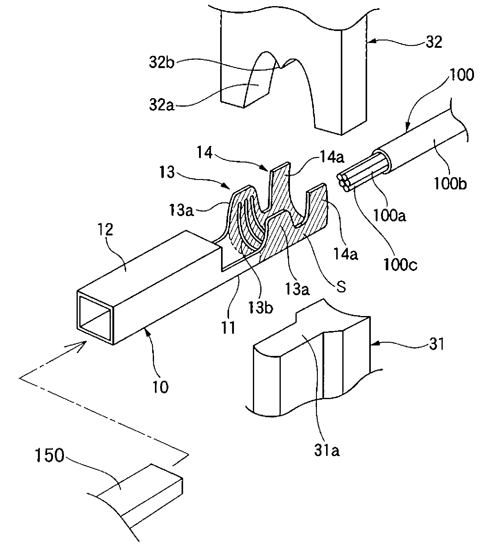
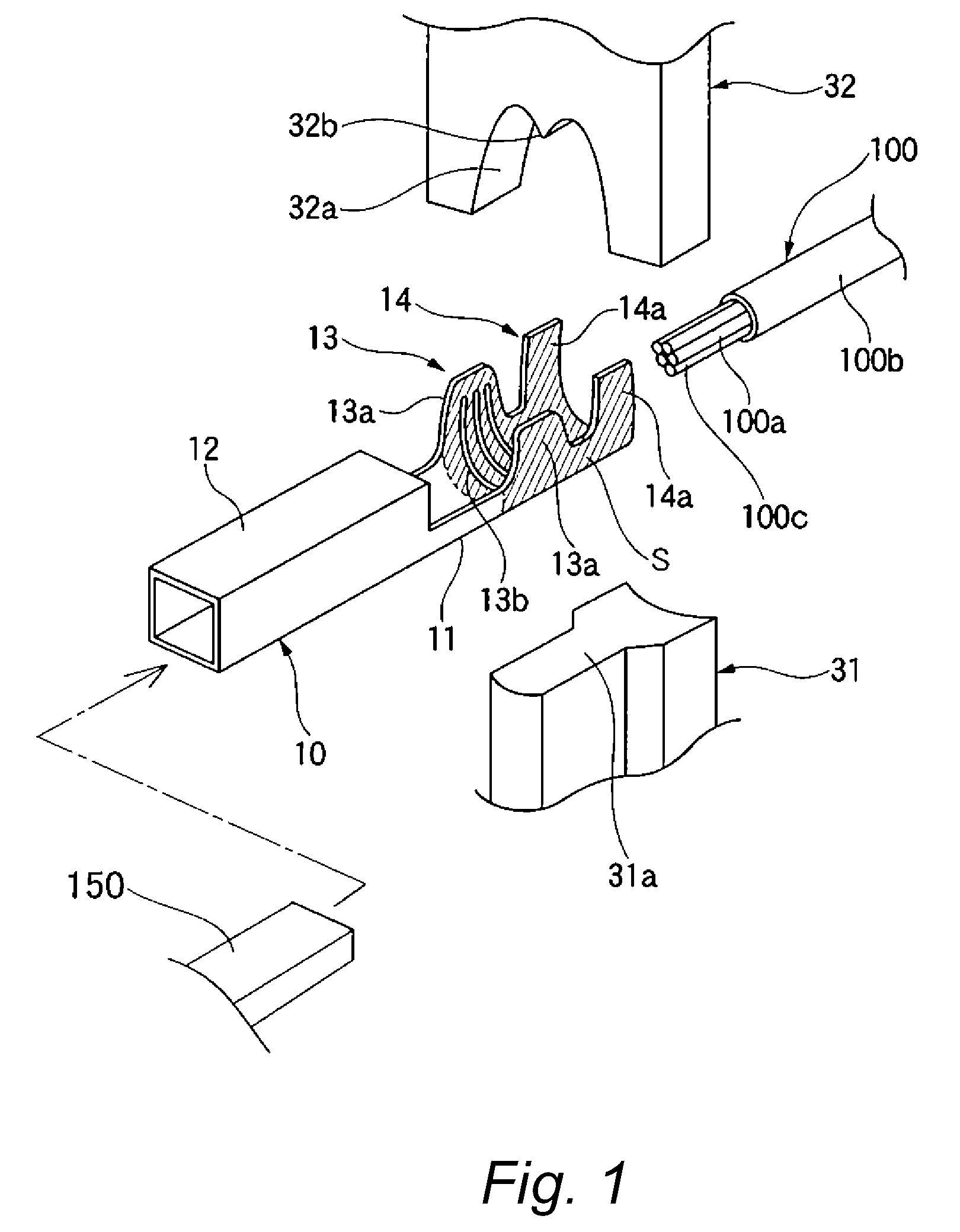
[0038]In FIG. 1, reference numeral 10 denotes a crimp terminal, reference numeral 100 denotes an aluminum electric wire, and reference numerals 31 and 32 denote a lower die and an upper die of a crimping jig, respectively. In this embodiment, the crimp terminal 10 is used in which a tin plating 52 is applied to a surface of a terminal base material 51 (refer to FIG. 5) of copper or a copper alloy in order to increase an electric connecting performance thereof. In addition, an aluminum electric wire 100 is such that an aluminum conductor 100a made up of a bundle of strands 100c which can take the form of twisted strands is held at a center of an insulation sheathing 100b.

[0039]The crimp terminal 10 includes an electric connecting portion 12 for electric connection with a mating terminal 150 (refer to FIG. 1) at a front end side in a longitudinal direction thereof (h...


PUM

PropertyMeasurementUnit
thicknessaaaaaaaaaa
thicknessaaaaaaaaaa
thicknessaaaaaaaaaa

Abstract

In order to promote the adhesion of a crimp terminal (10) to an aluminum electric wire (100) by virtue of crimping to thereby realize an improvement in electric connecting performance, the thickness of tin plating applied to an inner surface of a conductor crimping portion (13) of the crimp terminal (10) is set to be in the range from 2.1 μm to 5.0 μm, and then, the conductor crimping portion (13) is crimped to a conductor (100a) of the aluminum electric wire (100).

Description

TECHNICAL FIELD[0001]The present invention relates to a method for crimping a terminal to an aluminum electric wire.BACKGROUND ART[0002]A crimping method is widely used as a method for connecting a terminal and an electric wire. Crimping means a technique in which a conductor exposed portion of an electric wire is inserted into a conductor crimping portion and the electric wire is electrically connected to the conductor crimping portion by crimping the conductor crimping portion with a crimp tool or the like so as to embrace the conductor exposed portion therein. The conductor crimping portion has a substantially U-shape and is provided on a terminal.[0003]In order to improve the connecting performance by crimping, it is conventionally practiced to plate a surface of a terminal with tin to thereby increase the crimping performance. In the event that the terminal plated with tin in the way described above is crimped to an electric wire, it is known that the tin with which the termina...

Claims


Application Information

Patent Timeline
Patent Type & Authority Patents(United States)
IPC IPC(8): H01R43/04
CPCH01R4/185H01R4/188H01R4/26H01R4/62H01R43/048H01R13/035Y10T29/49185Y10T29/49183Y10T29/49181
Inventor KONDO, TAKAYASAKAGUCHI, TADAHISA
Owner YAZAKI CORP
Why Eureka
Try Eureka