
Extended wear ball lock for rotating head

a technology of rotating head and ball lock, which is applied in the direction of drilling pipes, drilling casings, borehole/well accessories, etc., can solve the problem of prolonging the downtime of the rotating head

Active Publication Date: 2012-08-21
PRUITT TOOL & SUPPLY
View PDF29 Cites 4 Cited by
  • Summary
  • Abstract
  • Description
  • Claims
  • Application Information

AI Technical Summary

Benefits of technology

"The present invention is a rotating head assembly for oil field equipment that has a simplified and cost-effective method of assembly and disassembly. It includes a box assembly with locking elements that secure the assembly, a simplified method of installing and uninstalling the seals, and an integrated seal surface on the inner barrel. The assembly also includes two metal encased spring loaded seals on each end of the inner barrel, which allow for a continuous pressurized flush of the internal cavity of the bearings. The invention also provides a safer working environment for rig personnel, increases efficiency of the assembly and disassembly process, and increases the life of the seals, bearings, and other internal components."

Problems solved by technology

Further, the use of bolts requires drilling personnel or other users to expend valuable time to both assemble and disassemble the rotating head thus leading to extended downtime of the rotating head.

Method used


Image

  • Extended wear ball lock for rotating head
  • Extended wear ball lock for rotating head
  • Extended wear ball lock for rotating head

Examples


Embodiment Construction

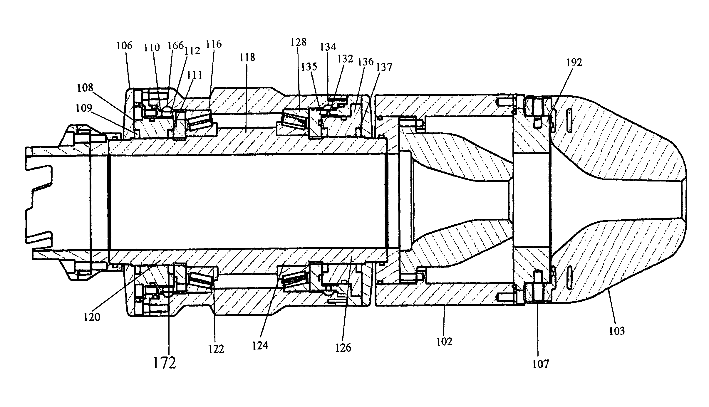
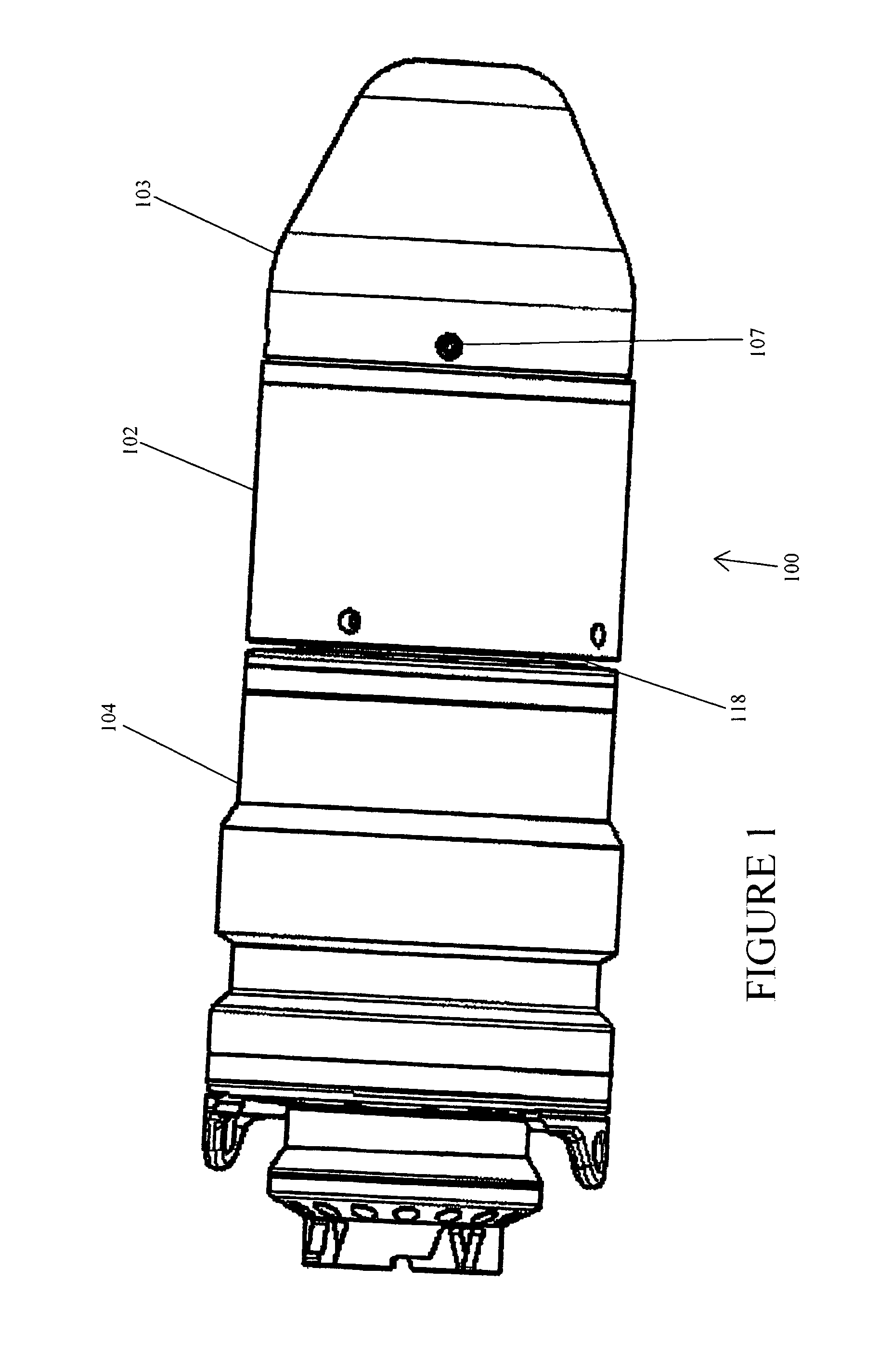
[0058]Referring to FIG. 1, the rotating head assembly of the present invention is generally illustrated by reference numeral 100. The rotating head assembly 100 is characterized by a bottom pot 102, an outer barrel 104, and a second rubber 103. Bottom pot 102 is releasably connected to inner barrel 118. As is shown in FIG. 1, bottom pot 102 is attached to second rubber 103 by the locking pin 107 of the rubber pot plate 192. Rubber pot plate 192 is securedly attached to bottom pot 102 by use of known fasteners such as threaded fasteners, including but not limited to bolts.

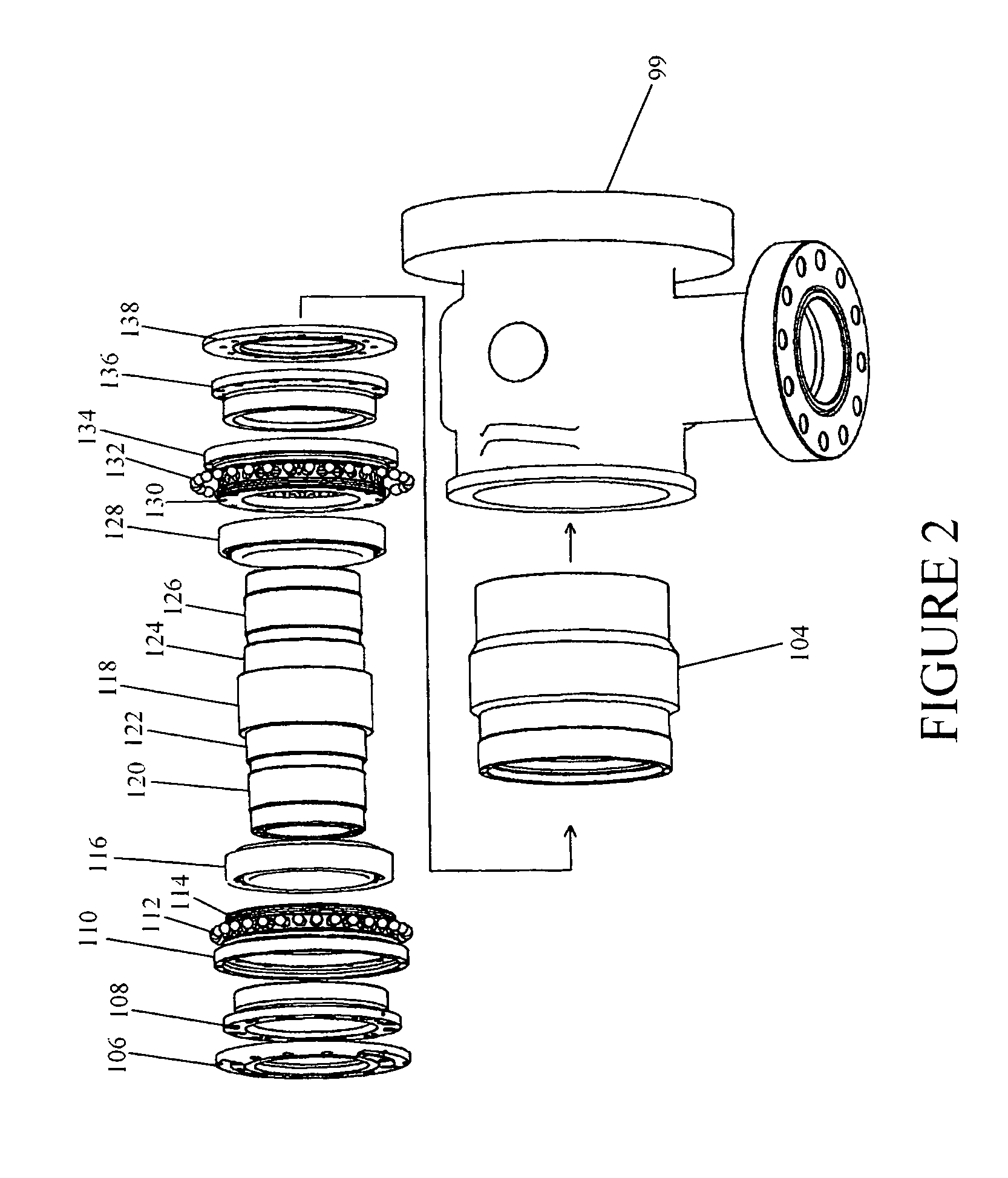
[0059]FIG. 2 shows an exploded view of the rotating head assembly 100 and the rotatable attachment of inner barrel 118 to outer barrel 104. As seen in FIGS. 2 and 10, plates 106, 138 are releasably attached to liners 108, 136 by a fastener including but not limited to threaded fasteners or other known fasteners. Plates 106, 138 prevent debris and other contaminants from entering the rotating head assembly. In one em...


PUM


Abstract

An improved rotating head that utilizes a box assembly that stores at least one locking element that allows for movement of the locking balls within the box assembly such that a liner inserted into the box assembly biases the locking elements to a locked position to couple the box assembly and the outer barrel. An integrated wear surface of the present invention seals the bearing elements to extend the life of the rotating head and reduce downtime caused by necessary maintenance of the rotating head.

Description

CROSS-REFERENCE TO RELATED APPLICATIONS[0001]This application claims priority to and is a continuation of U.S. patent application Ser. No. 12 / 074,151 filed on Feb. 29, 2008 now U.S. Pat. No. 7,870,896 entitled EXTENDED WEAR BALL LOCK FOR ROTATING HEAD.STATEMENT REGARDING FEDERALLY SPONSORED RESEARCH OR DEVELOPMENT[0002]Not Applicable.REFERENCE TO A MICROFICHE APPENDIX[0003]Not Applicable.RESERVATION OF RIGHTS[0004]A portion of the disclosure of this patent document contains material which is subject to intellectual property rights such as but not limited to copyright, trademark, and / or trade dress protection. The owner has no objection to the facsimile reproduction by anyone of the patent document or the patent disclosure as it appears in the Patent and Trademark Office patent files or records but otherwise reserves all rights whatsoever.BACKGROUND OF THE INVENTION[0005]1. Field of the Invention[0006]In well drilling, with a rotary drilling rig, the drill bit and drilling pipe recei...

Claims


Application Information

Patent Timeline
Patent Type & Authority Patents(United States)
IPC IPC(8): E21B19/00
CPCE21B33/085
Inventor PRUITT, GRANTBRAUN, CRIS
Owner PRUITT TOOL & SUPPLY
Learn More