
Laser surface treatment for mechanical seal faces

a sealing face and surface treatment technology, applied in the field of sealing rings, can solve the problems of sealing face damage, premature wear, seal ring damage, etc., and achieve the effect of avoiding or substantially minimizing surface ablation and substantially eliminating ablation

Active Publication Date: 2012-08-28
FLOWSERVE MANAGEMENT CO
View PDF15 Cites 4 Cited by
  • Summary
  • Abstract
  • Description
  • Claims
  • Application Information

AI Technical Summary

Benefits of technology

The invention is about a seal ring for rotating shafts that is designed to resist electro-corrosion, which is caused by a static electrical charge that develops between the seal faces. The seal faces are in close proximity to each other when the shaft is not rotating, and can easily come into contact with each other. This results in damage to the seal faces, which can be caused by pitting and other forms of damage. The invention proposes a solution to this problem by modifying the seal face properties with a laser process to minimize electro-corrosion. The technical effect of this invention is to provide a mechanical seal that is more resistant to electro-corrosion, which can cause damage and premature wear of the seal.

Problems solved by technology

While such mechanical seals are readily useable in a wide variety of environments, in specific sealing applications, for example, for the power industry and primarily for boiler feed seals in water, a particular electro-corrosion phenomenon occurs that results in damage to the seal faces.
This damage manifests itself in different forms, and for example, may manifest itself as pitting on the outer diameter of the silicon carbide (SiC) seal face.
This discharge is believed to result in damage to the seal rings and premature wear thereof.
However, the use of silicon carbide against silicon carbide results in a seal ring combination that is undesirable in that such seal rings are sensitive to damage when contact of the seal faces occurs which can happen during starts and stops of the shaft as well as operational upsets that might occur during normal operation of a pump which upsets may force the seal faces together and result in damage to the seal faces.
Further, it has been found that even silicon carbide versus silicon carbide can result in problems if these seal faces have a high ratio of electrical conductivity wherein surface damage can still occur.
This has had some success but not in every case.
This does result in additional expense, and may be limited by availability of space, and the improper application of such a device can possibly generate more charge and damage to other components in the pump / bearing / seal system.

Method used


Image

  • Laser surface treatment for mechanical seal faces
  • Laser surface treatment for mechanical seal faces
  • Laser surface treatment for mechanical seal faces

Examples


Embodiment Construction

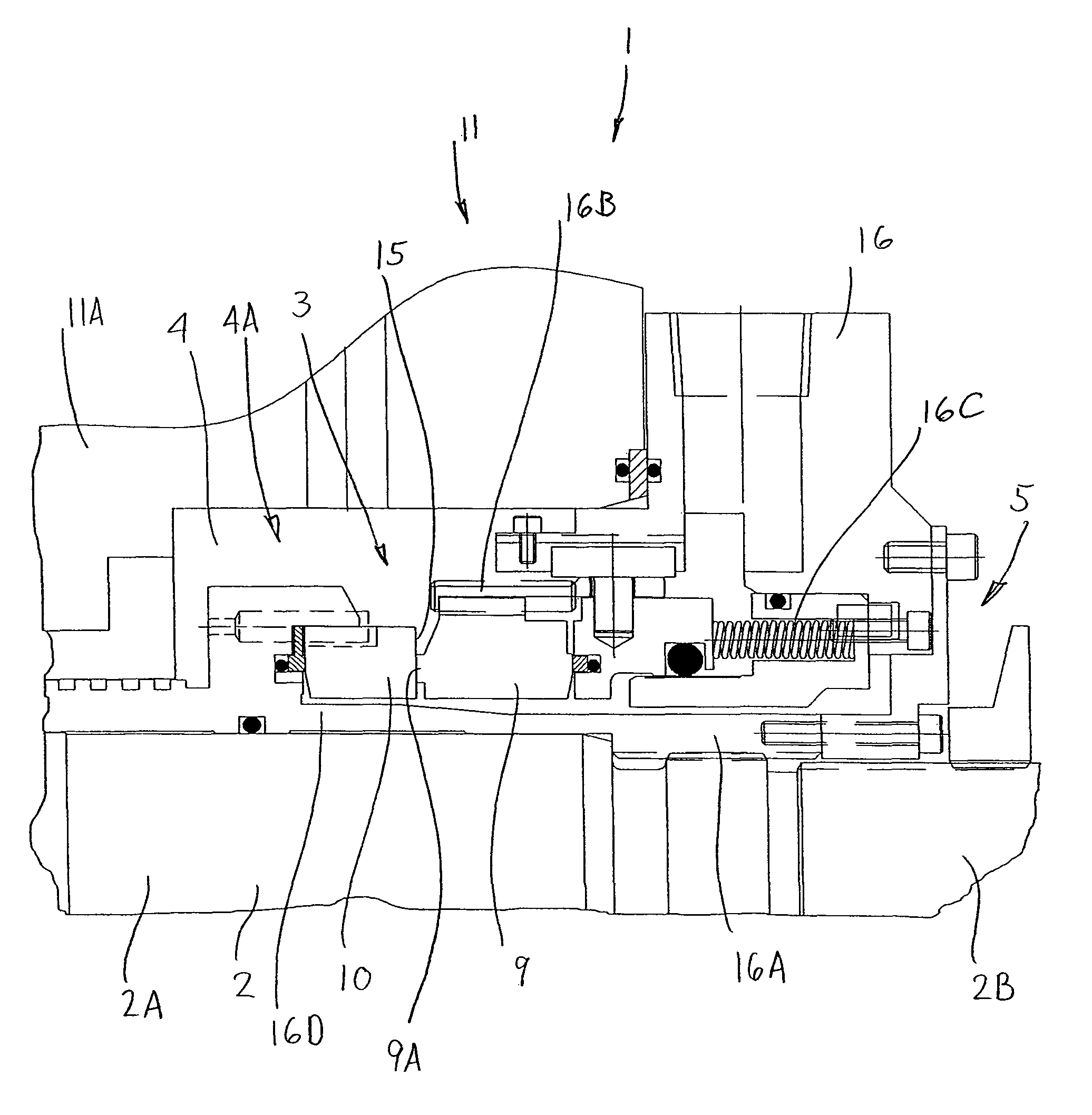
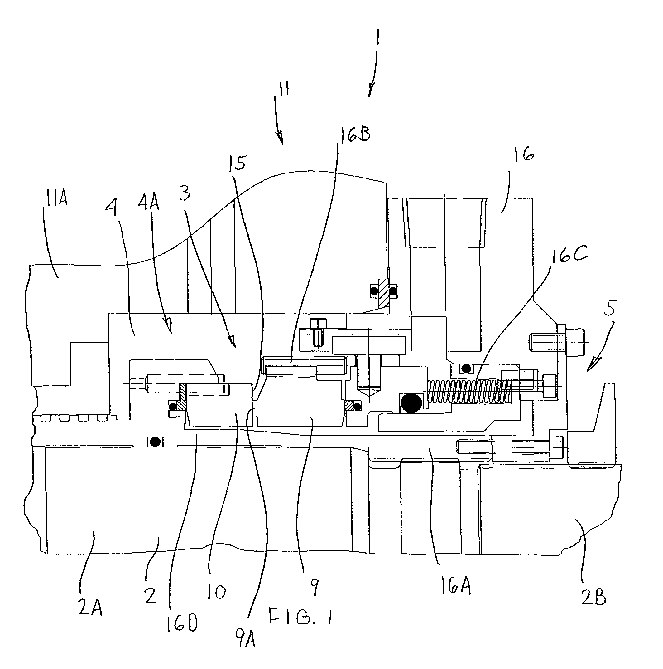
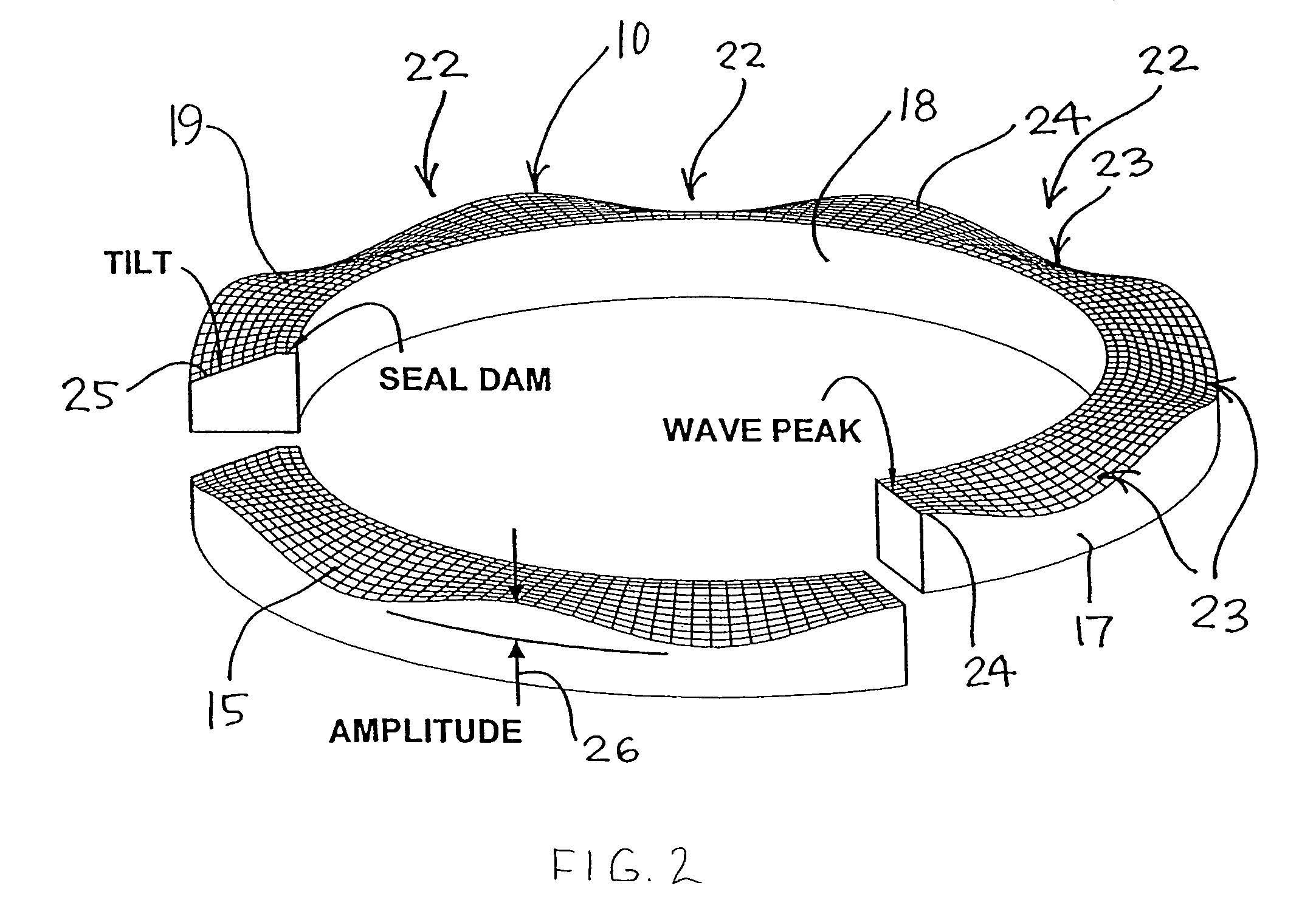
[0026]Referring to FIGS. 1, 2 and 3, the invention relates to a mechanical seal 1 which mounts to a rotatable equipment shaft 2, and specifically to the seal ring arrangement 3 thereof and the process for forming the seal ring arrangement 3 by which the material surface properties are modified to minimize electro-corrosion thereof.

[0027]Generally, the seal ring arrangement 3 sealingly separates a process fluid chamber 4 from the external seal environment 5 in a conventional manner. The seal ring arrangement generally includes a pair of opposed seal rings 9 and 10 (FIG. 1) which define a shaft seal to prevent leakage along the shaft 2 of rotary equipment 11, and the invention relates to a seal face treatment process using seal ring machining equipment 12 (FIG. 3) which has a laser unit 14 that forms micro-topography depth features in the seal face 15 of the seal ring 10 and / or performs a material surface treatment process to selectively redefine the material seal face properties so a...


PUM

PropertyMeasurementUnit
ultraviolet wavelength regionaaaaaaaaaa
thicknessaaaaaaaaaa
speedaaaaaaaaaa

Abstract

A seal ring arrangement generally includes a pair of opposed seal rings which define a shaft seal to prevent leakage along the shaft of rotary equipment. A seal face treatment process has been developed using seal ring machining equipment which has a laser unit that forms micro-topography depth features in the seal face and then performs a material surface treatment process to selectively alter the conductivity of the seal face so as to virtually eliminate electro-corrosion in the seal rings. The seal rings preferably are provided in a conventional combination of a carbide seal ring material for one of the seal rings and a silicon carbide material for the other seal ring. The laser machining and the laser treatment processes are preferably applied to the silicon carbide material.

Description

CROSS REFERENCE TO RELATED APPLICATION[0001]This application is a continuation-in-part of PCT Application No. PCT / US2008 / 003741, filed Mar. 21, 2008, which claims the benefit of U.S. Provisional Application Ser. No. 60 / 919,304, filed Mar. 21, 2007, which is incorporated herein by reference in its entirety.FIELD OF THE INVENTION[0002]The invention relates to a seal ring for rotating shafts and more particularly, relates to a seal ring having a seal face wherein the surface properties of the seal face are modified by a laser process applied to the seal face to minimize electro-corrosion in the seal face, and further relates to the laser surface treatment process for forming such a seal ring.BACKGROUND OF THE INVENTION[0003]To seal rotating shafts of pumps, compressors and the like, it is known to provide a non-contacting shaft seal on the shaft, which includes an axially adjacent pair of seal rings wherein one seal ring rotates with the shaft and the other seal ring is non-rotatably c...

Claims


Application Information

Patent Timeline
Patent Type & Authority Patents(United States)
IPC IPC(8): B21D53/84
CPCB23K26/0066F16J15/3424B23K26/0045Y10T29/49995Y10T29/49297B23K26/0006B23K26/352B23K2103/52
Inventor YOUNG, LIONEL
Owner FLOWSERVE MANAGEMENT CO
Learn More