Compositions and use thereof for modification of substrate surfaces

a technology of compositions and substrates, applied in the field of compositions, can solve the problems of difficult to achieve further reduction of pattern dimensions, limited dimensions of integrated circuit features, and regions exposed to radiation to become less removable with a developer solution or by conventional ic plasma processing

Active Publication Date: 2018-12-18
MERCK PATENT GMBH
View PDF23 Cites 0 Cited by
  • Summary
  • Abstract
  • Description
  • Claims
  • Application Information

AI Technical Summary

Benefits of technology

[0004]The grating of polymers on substrate surfaces also has been employed to impart anti-bio fouling of these surfaces or to improve their corrosion resistance.
[0005]Coating solutions, where the grafting of a polymer on a substrate surface can change the surface properties of these substrates to affect better coating; also in suspension of metal or metal oxide nanoparticles the coating ability and stability of these suspensions may be improved by the grafting of polymers at the surface of these nanoparticles.
[0008]In the graphoepitaxy directed self-assembly method, the block copolymers self organizes around a substrate that is pre-patterned with conventional lithography (Ultraviolet, Deep UV, e-beam, Extreme UV (EUV) exposure source) to form repeating topographical features such as a line / space (L / S) or contact hole (CH) pattern. In an example of a L / S directed self-assembly array, the block copolymer can form self-aligned lamellar regions which can form parallel line-space patterns of different pitches in the trenches between pre-patterned lines, thus enhancing pattern resolution by subdividing the space in the trench between the topographical lines into finer patterns. For example, a diblock copolymer which is capable of microphase separation and comprises a block rich in carbon (such as styrene or containing some other element like Si, Ge, Ti) which is resistant to plasma etch, and a block which is highly plasma etchable or removable, can provide a high resolution pattern definition. Examples of highly etchable blocks can comprise monomers which are rich in oxygen and which do not contain refractory elements, and are capable of forming blocks which are highly etchable, such as methylmethacrylate. The plasma etch gases used in the etching process of defining the self-assembly pattern typically are those used in processes employed to make integrated circuits (IC). In this manner very fine patterns can be created in typical IC substrates than were definable by conventional lithographic techniques, thus achieving pattern multiplication. Similarly, features such as contact holes can be made denser by using graphoepitaxy in which a suitable block copolymer arranges itself by directed self assembly around an array of contact holes or posts defined by conventional lithography, thus forming a denser array of regions of etchable and etch resistant domains which when etched give rise to a denser array of contact holes. Consequently, graphoepitaxy has the potential to offer both pattern rectification and pattern multiplication.
[0009]In chemical epitaxy or pinning chemical epitaxy the self-assembly of the block copolymer is formed around a surface that has regions of differing chemical affinity but no or very slight topography to guide the self-assembly process. For example, the surface of a substrate could be patterned with conventional lithography (UV, Deep UV, e-beam EUV) to create surfaces of different chemical affinity in a line and space (L / S) pattern in which exposed areas whose surface chemistry had been modified by irradiation alternate with areas which are unexposed and show no chemical change. These areas present no topographical difference, but do present a surface chemical difference or pinning to direct self-assembly of block copolymer segments. Specifically, the directed self-assembly of a block copolymer whose block segments contain etch resistant (such as styrene repeat unit) and rapidly etching repeat units (such as methyl methacrylate repeat units) would allow precise placement of etch resistant block segments and highly etchable block segments over the pattern. This technique allows for the precise placement of these block copolymers and the subsequent pattern transfer of the pattern into a substrate after plasma or wet etch processing. Chemical epitaxy has the advantage that it can be fined tuned by changes in the chemical differences to help improve line-edge roughness and CD control, thus allowing for pattern rectification. Other types of patterns such as repeating contact holes (CH) arrays could also be pattern rectified using chemoepitaxy.
[0011]There is a need for a novel materials which can form a grafted polymer layer on semiconductor (e.g. Si, GaAs, and the like), metal (Cu, W, Mo, Al, Zr, Ti, Hf, Au and the like) and metal oxide (Copper oxide, Aluminum oxide, Hafnium oxide, Zirconium oxide, Titanium oxide and the like) substrates through a simple spin coating, followed by a post coat bake to affect chemical bonding without the presence of activating components to promote the grafting reaction on the substrate such as acidic compounds, thermal acid generators, photoacid generator, thermal radical generators, photochemical radical generators, basic additives, thermal base generators or photobase generators. The presence of such thermally or photochemically reactive additives compounds is undesirable because the small size and reactivity of these compounds, they may lead them to diffuse out of the grafted film into other layers causing undesirable reaction such as corrosion. Another need is for a grafting material in which graftable polymer does not contain overly reactive grafting sites which may deleteriously affect shelf life of solutions of a grafting solution in an organic solvent such as a spin casting solvent. There is also a need for novel grafting material than can be made to have selective grafting towards specific types of substrates by altering grafting bake. In this manner one can alter the surface properties of these materials, such as coat-ability, and corrosion resistance by a simple spin coating process without having to use plasma deposition or electrochemical grating, and also in the case of a novel selective grafting process using the novel materials of this invention, in one step coat only one type of material on a substrate which contains a topographical or chemical pattern in which different materials are present on one substrate. There is also a need for novel neutral layer compositions which when formed into a layer remain neutral to the self-assembly block copolymer and yet are not damaged by processing steps of directed self-assembly techniques, and can further enhance the lithographic performance of the directed self-assembly materials and processes, especially reducing the number of processing steps and providing better pattern resolution with good lithographic performance. There is also a need for coat-able pinning materials for small areas of metal or metal oxide substrates otherwise coated with a neutral layer, for instance in the chemoepitaxy approach, in order to force the domains oriented perpendicularly with the neutral layer substrate to force the alignment of the domains in a desired direction. There is also a need for a grafting composition that will selectively only graft on one type of material on a substrate containing a pattern with different materials to create a pinning area.

Problems solved by technology

Conversely, in negative photoresists, UV radiation transmitted through a mask causes the regions exposed to radiation to become less removable with a developer solution or by conventional IC plasma processing.
When using conventional lithographic exposure processes, the dimensions of features of the integrated circuit feature are limited.
Further reduction in pattern dimensions are difficult to achieve with radiation exposure due to limitations related to aberrations, focus, proximity effects, minimum achievable exposure wavelengths and maximum achievable numerical apertures.
The need for large-scale integration has led to a continued shrinking of the circuit dimensions and features in the devices.
In the past, the final resolution of the features has been dependent upon the wavelength of light used to expose the photoresist, which has its own limitations.
The presence of such thermally or photochemically reactive additives compounds is undesirable because the small size and reactivity of these compounds, they may lead them to diffuse out of the grafted film into other layers causing undesirable reaction such as corrosion.

Method used


Image

  • Compositions and use thereof for modification of substrate surfaces
  • Compositions and use thereof for modification of substrate surfaces
  • Compositions and use thereof for modification of substrate surfaces

Examples


synthesis example 2

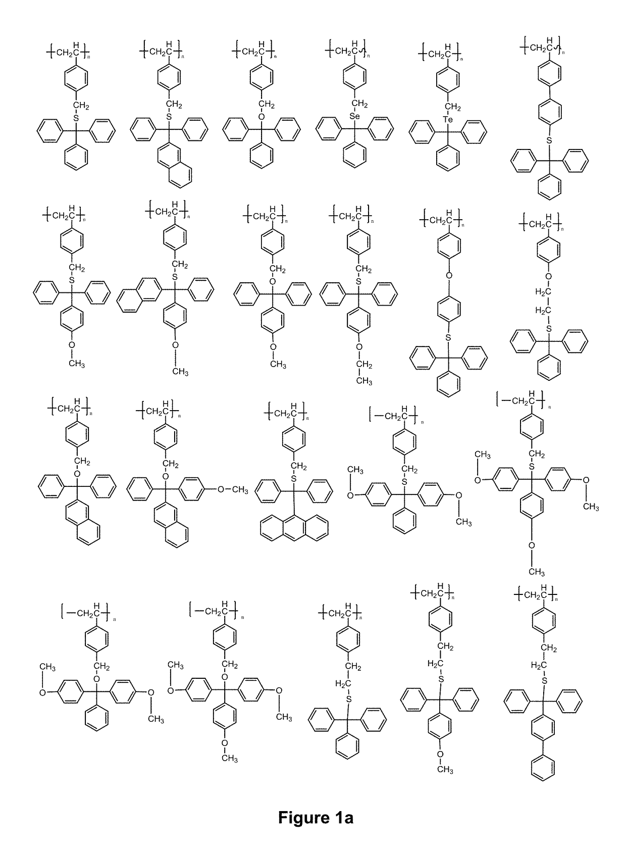
(mmt=4-Monomethoxytrityl) (IX)

[0128]

[0129]A 3 L flask was charge with 60 g of sodium hydrosulfide hydrate dissolved in a mixture of 700 g acetone / 700 g water and this solution was degassed to remove air by bubbling into it N2. To this flask was then added 60 g of 4-monomethoxytrityl chloride dissolved in 250 g of warm acetone. The mixture was stirred at room temperature for 2 hrs. The formed mmt-SH solid was isolated by filtering and washed thoroughly by DI water and finally dried in a room temperature (rt) vacuum oven until constant weight to obtain 52 g mmt-SH. Proton NMR confirmed the structure (in CDCl3, 14 phenyl H at 6.8-7.4 ppm; 3H in —OCH3 at 3.8 ppm and 1H in SH at 3.15 ppm)

Synthesis Example 3: Synthesis of Polystyrene Endcapped with CH2CH2—S-mmt (mmt=4-Monomethoxytrityl) (X)

[0130]

[0131]Under nitrogen gas protection, 100.3 g of the polymer made in example 1 was dissolved in 460 g of methylene chloride and charged into a 3 L flask. To this was added 30 g of p-toluenesulfonyl...

synthesis example 4

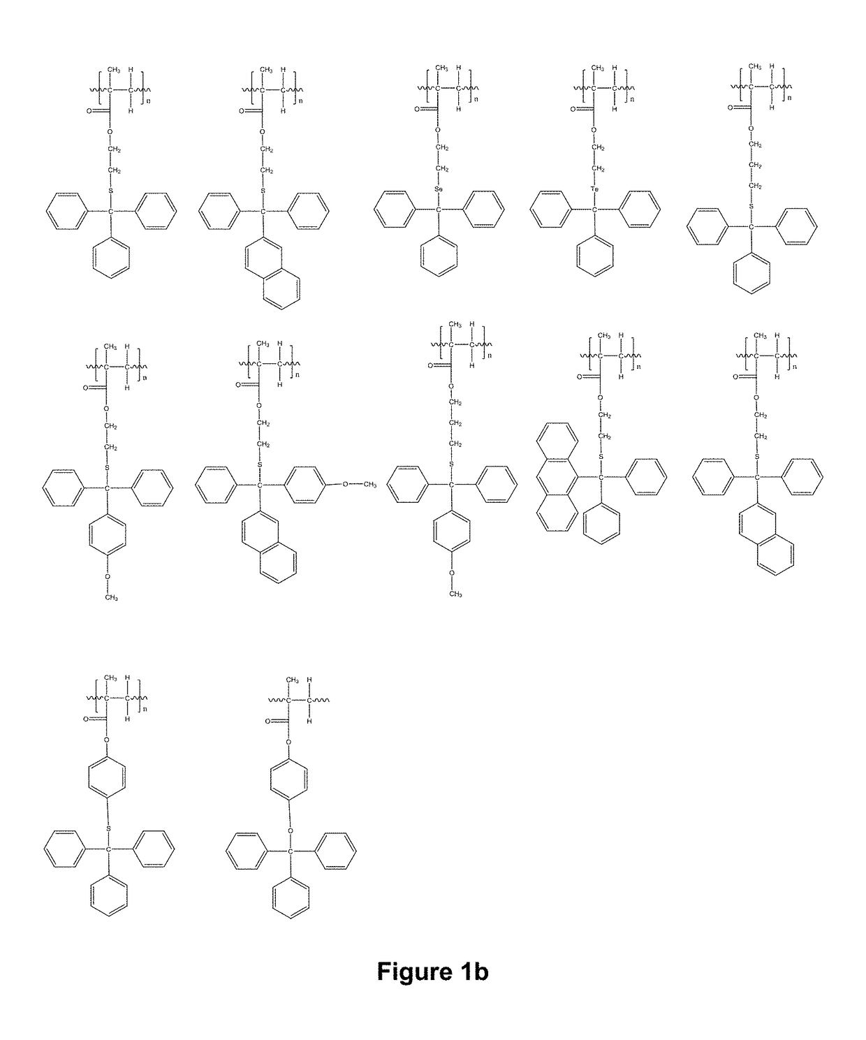
r with the Following Structure (XI)

[0133]

[0134]In a flask equipped with a magnetic bar and a cold water condenser, 0.59 g of 2-chloroethyl methacrylate, 0.6 g of AIBN and 19.6 g of methyl methacrylate were dissolved in 45 g of methyl ethyl ketone and the solution was purged with nitrogen gas for 30 min. The flask was immersed in an 80° C. oil bath. The reaction was then kept at this temperature for 5 hrs. After cooling, the polymer solution was slowly poured into methanol with vigorous agitation. The polymer obtained was isolated by filtering and dried in a 45° C. vacuum oven until constant weight to obtain 15 g of white polymer.

[0135]Under the protection of a nitrogen atmosphere, 0.7 g of mmt-SH made in Synthesis Example 2 was dissolved in 3 g of THF, and then 1.78 g of 1M potassium tert-butoxide in THF was added to this solution. After stirring at rt for about 10 min, 8 g of the polymer as made above was dissolved in 20 g of THF and added to this solution. The resultant reaction m...

synthesis example 5

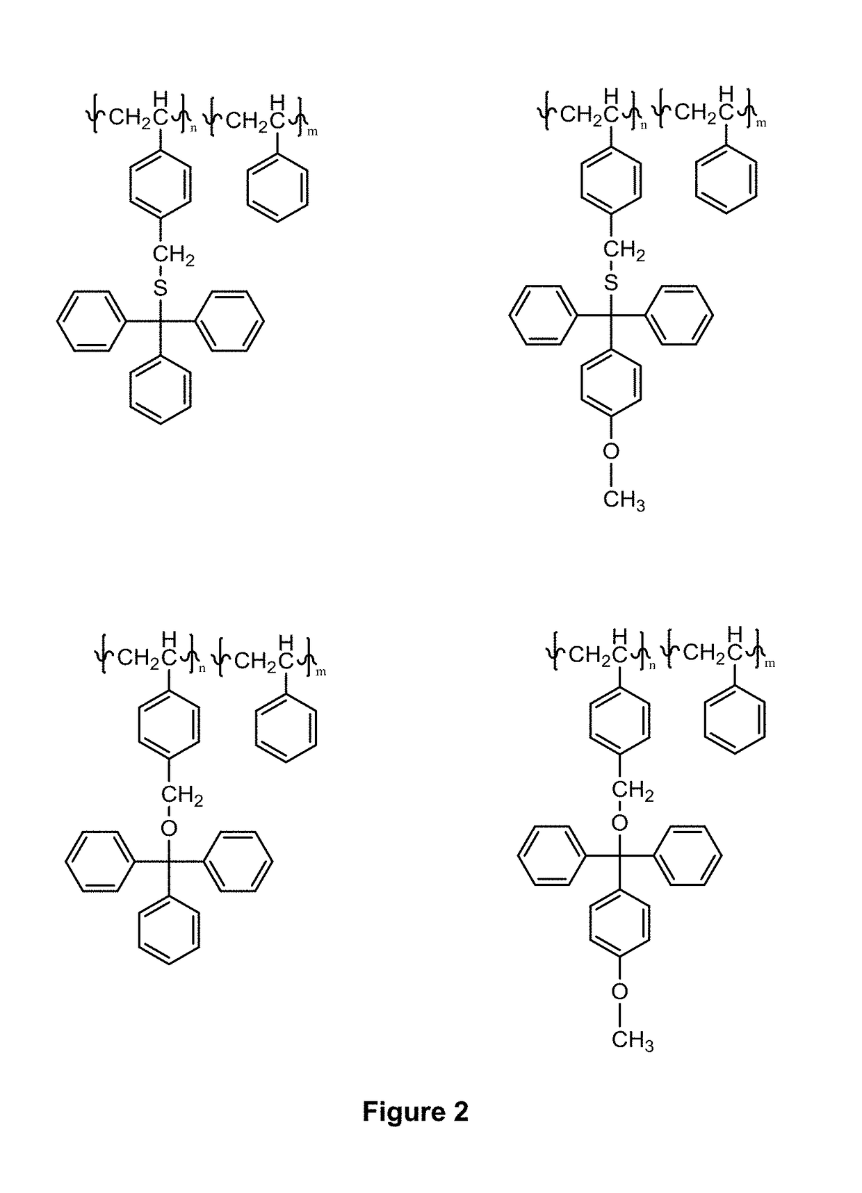
r with the Following Structure (XIII)

[0136]

[0137]In a flask equipped with a magnetic stirring bar and a cold water condenser, 0.66 g of 4-vinylbenzyl chloride, 1.0 g of AIBN and 20.4 g of styrene were dissolved in 45 g of methyl ethyl ketone and the solution was purged with nitrogen gas for 30 min. The flask was the immersed in a 80° C. oil bath. The reaction was kept at this temperature for 5 hrs. After cooling, the polymer solution was slowly poured into methanol with vigorous agitation. The polymer obtained was isolated by filtering and dried in a 45° C. vacuum oven until constant weight to obtain 11 g of white polymer.

[0138]Under nitrogen protection 0.71 g of mmt-SH made in Synthesis Example 2 was dissolved in 3 g of THF and 1.78 g of 1M potassium tert-butoxide in THF was added. After stirring at rt for about 10 min, 8 g of the polymer made above issolved in 20 g of THF was added. The reaction mixture was stirred at 50° C. for 24 hrs. The solution was then cooled and poured into...


PUM

PropertyMeasurementUnit
temperatureaaaaaaaaaa
thicknessaaaaaaaaaa

Abstract

The present invention relates to non aqueous, graftable coating composition comprised of a homogenous solution of a polymer and a spin casting organic solvent, where the composition does not contain acidic compounds, coloring particles, pigments or dyes, and the polymer has a linear polymer chain structure which is comprised of repeat units derived from monomers containing a single polymerizable olefinic carbon double bond, and the polymer contains at least one triarylmethyl chalcogenide containing moiety which is selected from the group consisting of repeat units having structure (I) an end chain group unit of structure (II) and mixtures thereof, and the polymer does not contain any repeat units or end groups containing water ionizable groups, ionic groups, free thiol groups, or free hydroxy groups, and where A1, A2, and A3 are independently an Aryl or a substituted Aryl; Y is a chalcogen selected from O, S, Se or Te; X1 and X2 are individually selected organic spacers; P1 is an organic polymer repeat unit moiety derived from a monomer containing a single polymerizable olefinic carbon double bound, and P2 is an end group moiety derived from a monomer containing a single polymerizable olefinic carbon double bound, and represents a direct valence bond to the linear polymer.The invention also relates to using this novel coating composition to form a grafted polymer film on a substrate.

Description

FIELD OF THE INVENTION[0001]The invention relates to novel grafting compositions containing polymers with at least one attached triarylmethyl chalcogenide moiety and a solvent. The invention also related to the process of forming grafted films on a substrate using these compositions and using the grafted films on a substrate for self-assembly.DESCRIPTION OF THE INVENTION[0002]Grafted polymer which form covalently bound film on the surface of a substrate can be prepared by plasma deposition, electrochemical deposition or self-assembly. The strength of covalent bond predicates the adherence of film, however, these film are generally much more adherent than films which only interact through secondary forces with the surface of the substrate such as those prepared by spin casting. Consequently, because of this higher adherence formation of a grafted polymer film on a substrate material is useful for a variety of applications. Among these are:[0003]One example are biomaterials where subs...

Claims


Application Information

Patent Timeline
Patent Type & Authority Patents(United States)
IPC IPC(8): C09D151/00H01L21/02C09D133/08C09D135/06B05D3/02H01L21/324H01L21/027
CPCC09D151/003B05D3/02C09D133/08H01L21/324H01L21/0271H01L21/02118C09D135/06B05D3/0254
Inventor LIN, GUANYANGWU, HENGPENGKIM, JIHOONYIN, JIANBASKARAN, DURAIRAJSHAN, JIANHUI
Owner MERCK PATENT GMBH
Why Eureka
Try Eureka