Turbine airfoil with near wall vortex cooling

a technology of turbine airflow and vortex cooling, which is applied in the direction of liquid fuel engines, marine propulsion, vessel construction, etc., can solve the problems of reducing the efficiency of the engine by cooling air, the lowest turbine inlet temperature is limited to the material properties of the turbine, and the rotor blade and stator vanes have different design constraints, etc., and achieves the effect of low flow

Inactive Publication Date: 2012-08-28
FLORIDA TURBINE TECH
View PDF4 Cites 32 Cited by
  • Summary
  • Abstract
  • Description
  • Claims
  • Application Information

AI Technical Summary

Benefits of technology

[0010]It is an object of the present invention to provi

Problems solved by technology

Rotor blades and stator vanes have different design constraints due to the rotor blades being exposed to large centrifugal forces from rotation while the stator vanes are exposed to bending forces.
However, the highest turbine inlet temperature is limited to the material properties of the turbine, mainly the first stage airfoils, and the amount of cooling that can be produced for these airfoils.
Since the pressurized air used for cooling of these airfoils is bled off from the compressor, the cooling air decreases the efficiency of the engine because work is performed to compressor the cooling air and no useful work are extracted from the compressed cooling air.
For the cooling of the airfoil wall, resupply holes and spanwis

Method used


Image

  • Turbine airfoil with near wall vortex cooling
  • Turbine airfoil with near wall vortex cooling
  • Turbine airfoil with near wall vortex cooling

Examples


Embodiment Construction

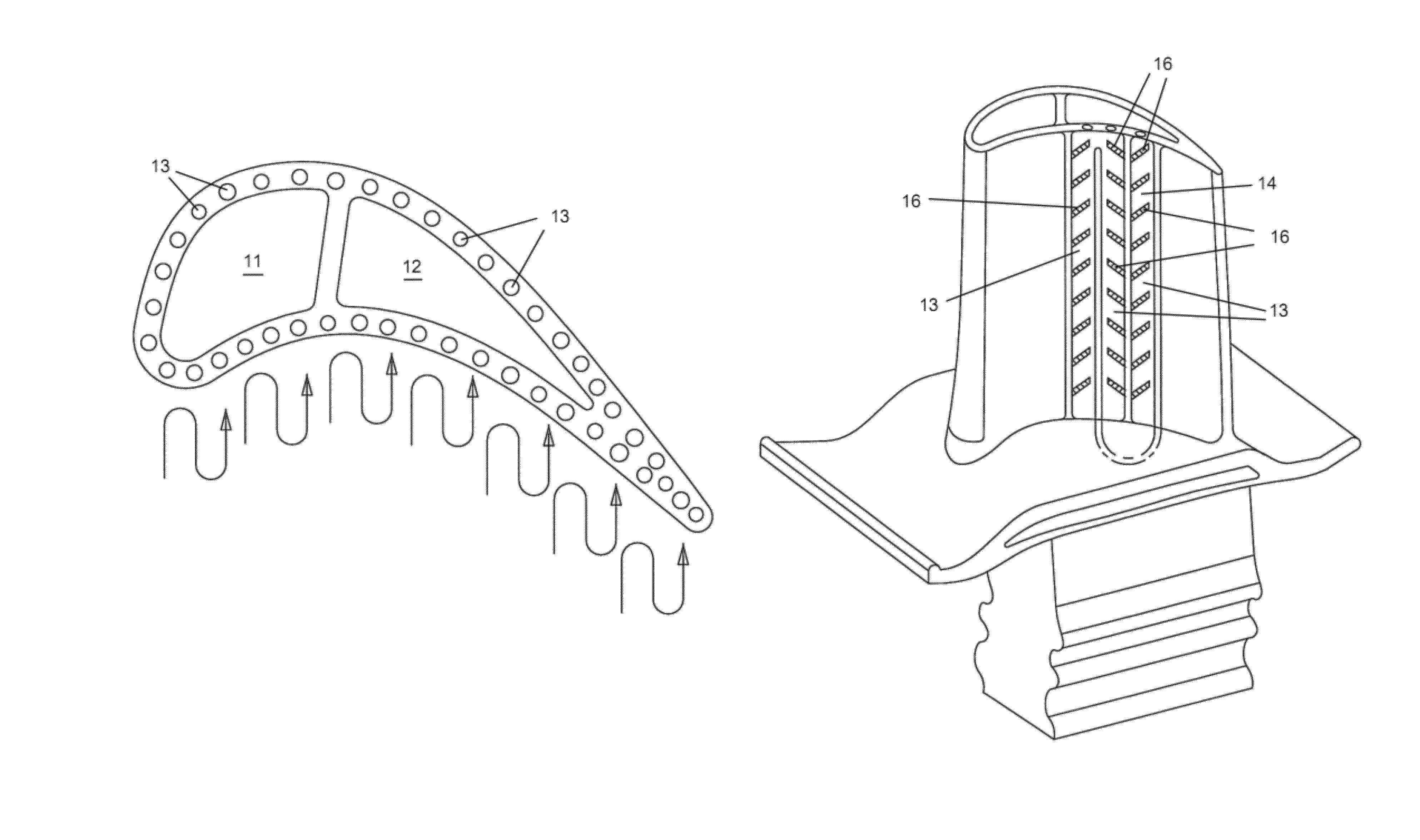
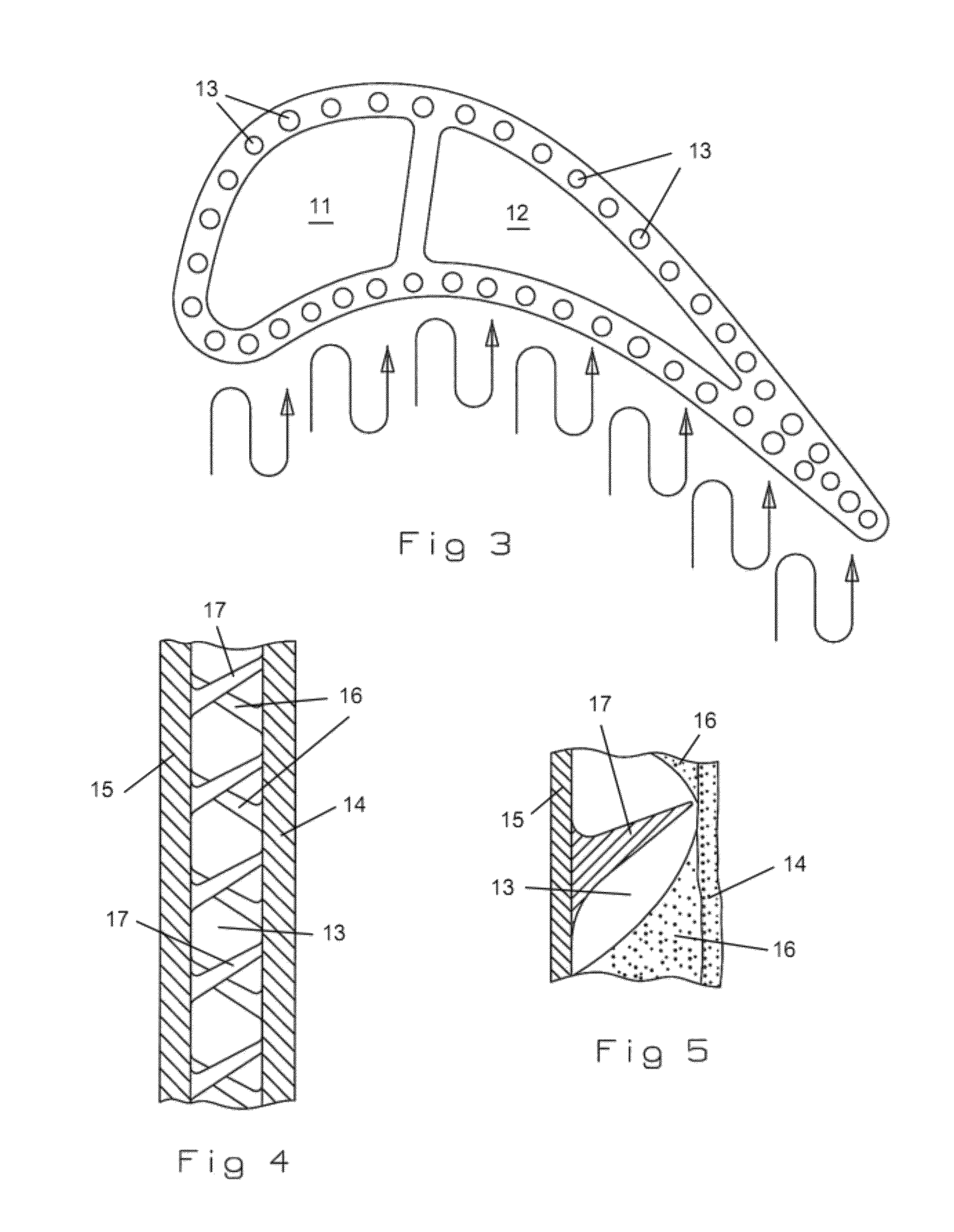
[0022]A cross section view of the airfoil with near wall mini vortex flow radial channels 13 is shown in FIG. 3 and includes walls that form the airfoil shape that extend from a leading edge to a trailing edge, and a rib extending across the walls to form two separate a forward cavity 11 from an aft cavity 12. The radial channels 13 are formed between a main spar that forms the support for a thin thermal skin that is bonded to the spar to form the airfoil surface of the blade or vane. As seen in FIG. 3, the radial channels 13 extend around the entire airfoil and into the trailing edge region in which no internal cavity is formed between the pressure side wall and the suction side wall. In one embodiment, the radial channels are single radial channels that each open onto the tip through tip holes to discharge the cooling air from the radial channel and cool the blade tip for the blade embodiment. In another embodiment as seen in FIG. 3 by the diagram, the radial channels form a serpe...


PUM


Abstract

A turbine airfoil having walls with radial extending near wall cooled vortex flowing channels to provide for a high cooling effectiveness with a low cooling flow requirement. A thermal skin is bonded over a main spar in which skewed ribs extend from both the spar and the thermal skin to form a vortex flowing path along the radial channels. The vortex flowing radial channels can be single pass radial channels or connected to form a 3-pass serpentine flow circuit with tip holes to discharge the cooling air from the radial channels and cool the blade tip periphery.

Description

GOVERNMENT LICENSE RIGHTS[0001]None.CROSS-REFERENCE TO RELATED APPLICATIONS[0002]None.BACKGROUND OF THE INVENTION[0003]1. Field of the Invention[0004]The present invention relates generally to a gas turbine engine, and more specifically to a turbine airfoil with near wall low flow cooling.[0005]2. Description of the Related Art[0006]Including Information Disclosed Under 37 CFR 1.97 and 1.98[0007]A gas turbine engine includes a turbine with multiple rows or stages of rotor blades and stator vanes each with an airfoil that reacts with a hot gas flow. Rotor blades and stator vanes have different design constraints due to the rotor blades being exposed to large centrifugal forces from rotation while the stator vanes are exposed to bending forces. However, both blades and vanes have airfoils that require cooling in order to withstand the high gas flow temperatures, especially for the first stage airfoils.[0008]In order to increase the turbine efficiency, and therefore the engine efficien...

Claims


Application Information

Patent Timeline
IPC IPC(8): F01D5/18
CPCF01D5/187F05D2240/127F05D2250/185F05D2260/2212F05D2260/22141F05D2250/25
Inventor LIANG, GEORGE
Owner FLORIDA TURBINE TECH
Why Eureka
Try Eureka