Walking assistance device

a technology of assistance device and walking aid, which is applied in the direction of walking aids, physical therapy, chiropractic devices, etc., can solve the problems of difficult to cause an assisting force, difficult to generate such an assisting force at each leg portion of the walking assistance device, and unsatisfactory reduction of load on the user, so as to reduce the propulsion power and reduce the load on the user

Active Publication Date: 2012-08-28
HONDA MOTOR CO LTD
View PDF14 Cites 64 Cited by
  • Summary
  • Abstract
  • Description
  • Claims
  • Application Information

AI Technical Summary

Benefits of technology

[0003]The walking assistance device described in the aforesaid Patent Document 1 is capable of generating a target propulsion power in a direction in which the user is moving (a force for assisting a motion of a free leg of the user), thereby to reduce the propulsion power required to be generated by the user himself / herself. However, as is obvious from FIG. 15 in Patent Document 1, the weight of the user has to be supported by the user himself / herself. This has led to unsatisfactorily reduced load on the user.

Problems solved by technology

This has led to unsatisfactorily reduced load on the user.
In addition, the one in Patent Document 1 does not have a technology for setting a target value of an acting force between the walking assistance device and the user according to a motion state of each leg of the user.
This has been making it difficult to cause an assisting force suited to a motion state of each leg of the user to act on each leg of the user.
However, in the one disclosed in Patent Document 1, it is difficult to generate such an assisting force at each leg portion of the walking assistance device.
This requires complicated dynamic calculation or the like to generate appropriate driving forces for the joints.
Further, in this case, the influences of modeling errors of dynamic models or calculation errors or the like frequently lead to inappropriate target values of driving forces for joints with respect to motions of the legs of the user.
Hence, there has been a danger that a load on the user rather increases, depending on motion states of the legs of the user.

Method used


Image

  • Walking assistance device
  • Walking assistance device
  • Walking assistance device

Examples


first embodiment

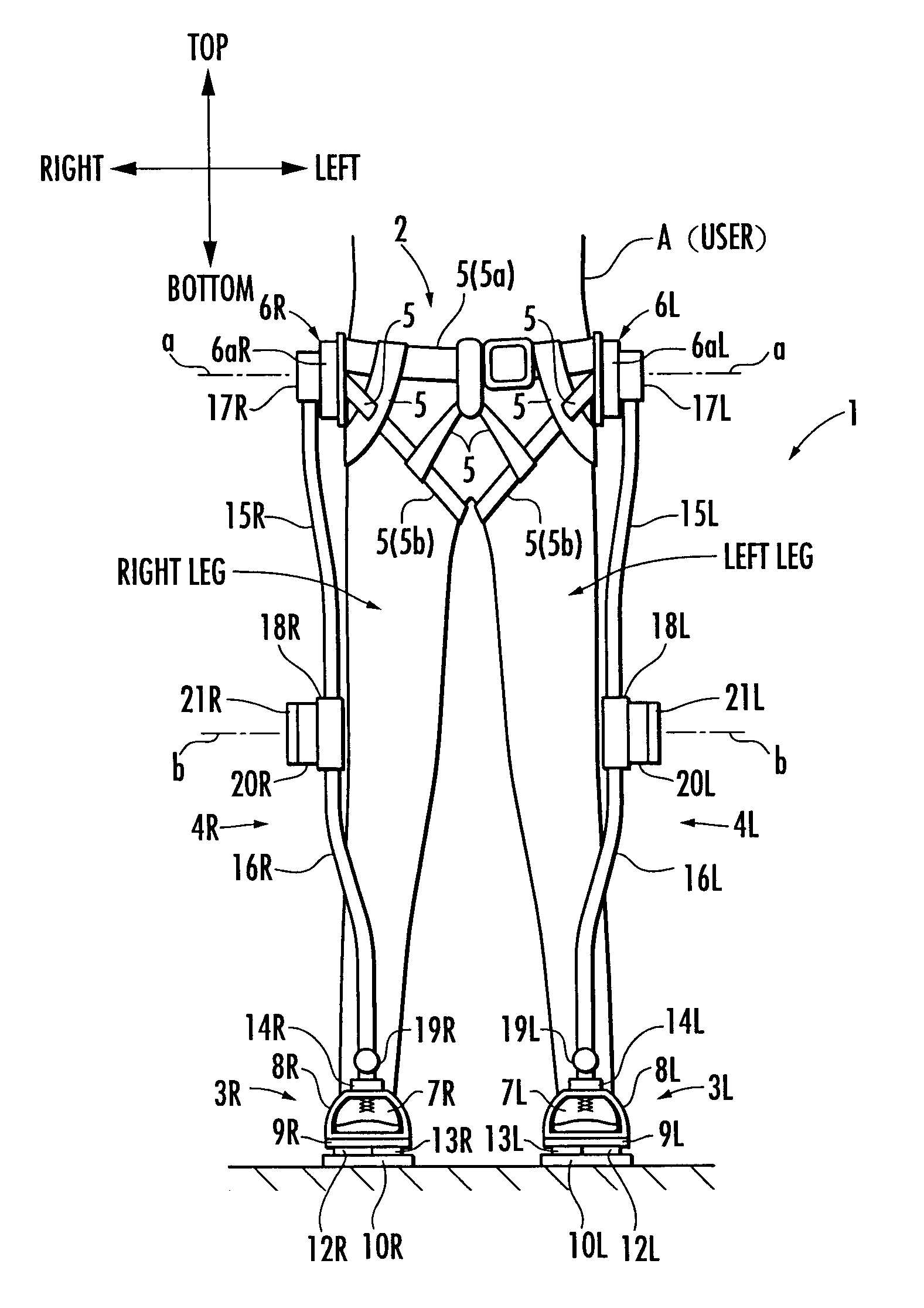
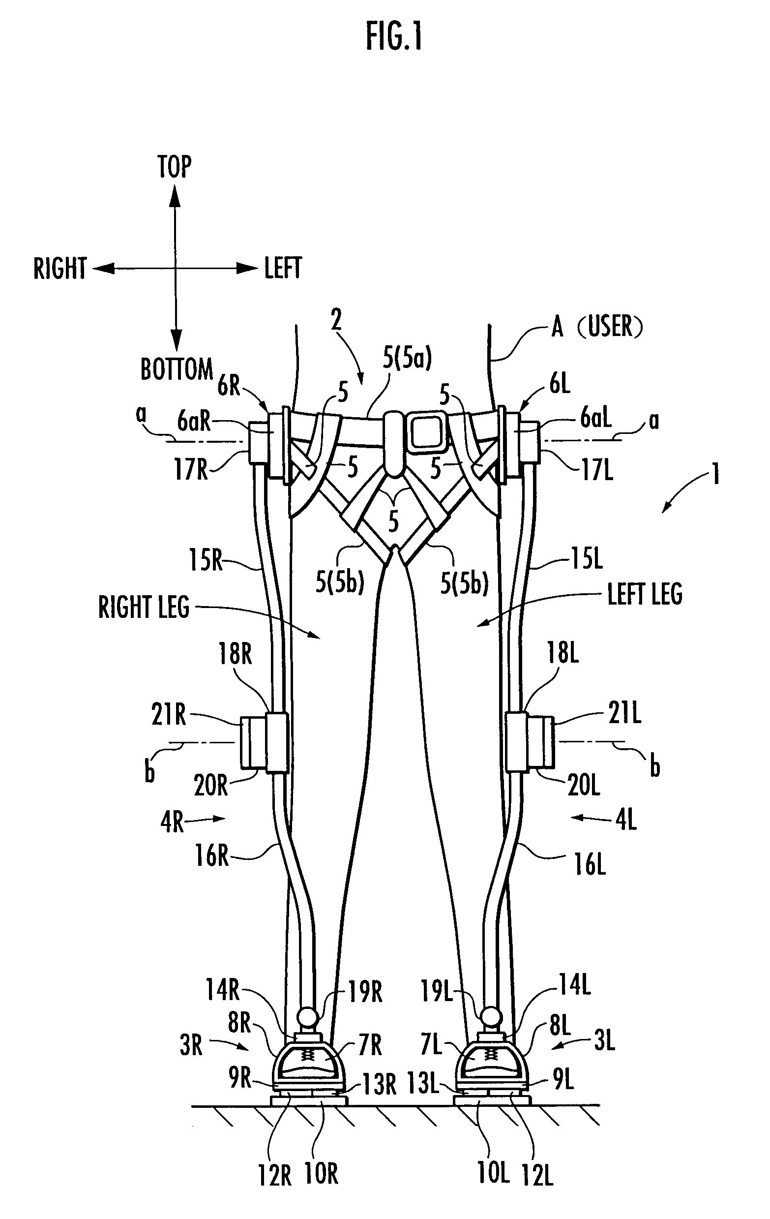
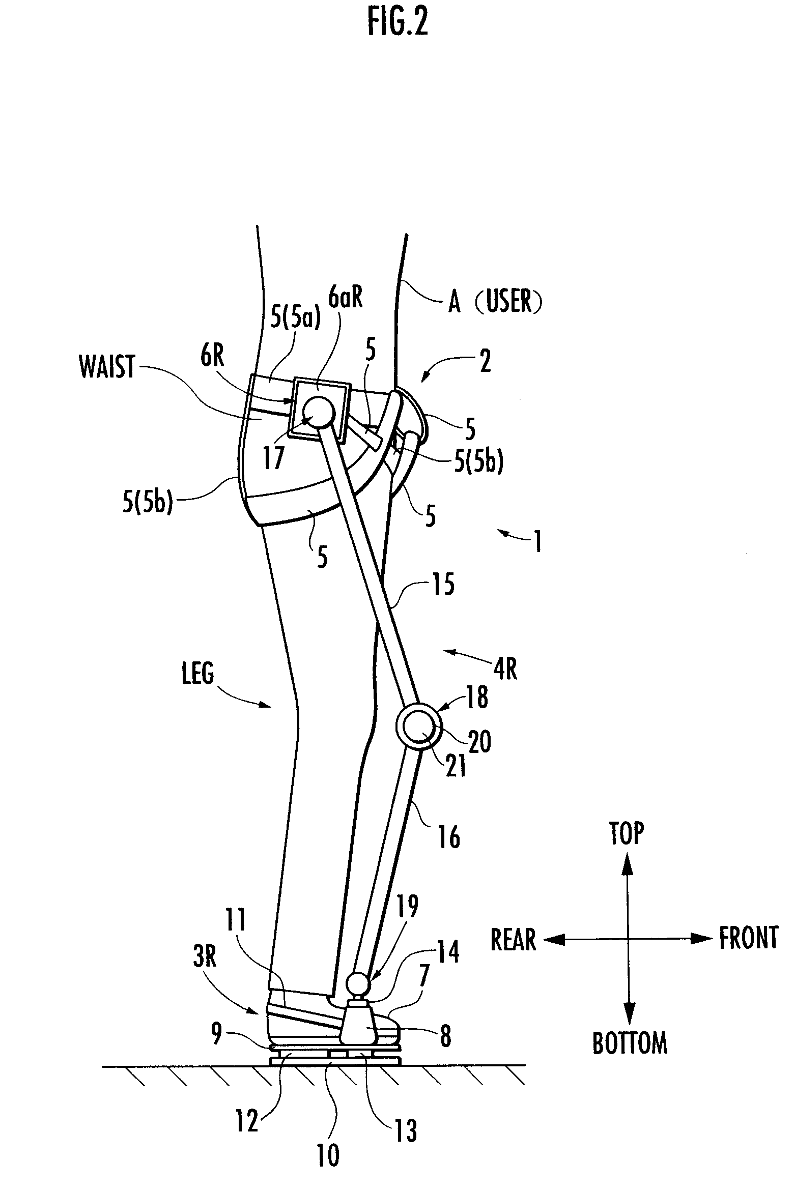
[0027]The following will explain the present invention with reference to FIG. 1 to FIG. 4. First, referring to FIG. 1 and FIG. 2, the structure of a walking assistance device according to the present embodiment will be explained. FIG. 1 is a diagram showing the walking assistance device according to the present embodiment and a user wearing the device viewed from the front (a diagram observed in a frontal plane), and FIG. 2 is a diagram showing the walking assistance device and the user viewed sideways (a diagram observed in a sagittal plane).

[0028]Referring to FIG. 1 and FIG. 2, a walking assistance device 1 according to the present embodiment is provided with a body-mounted assembly 2 to be attached to the waist of a user A, a pair of left and right foot-mounted assemblies 3L, 3R to be attached to the left and right feet of the user A, and a pair of left and right leg links 4L, 4R, which connect the foot wear assemblies 3L and 3R, respectively, to the body wear assembly 2. The foo...

third embodiment

[0106]A third embodiment according to the present invention will now be explained with reference to FIGS. 8(a) and (b). FIGS. 8(a) and (b) are diagrams of a front view and a side view, respectively, of a portion near the waist of a walking assistance device according to the present embodiment and a user wearing the same.

second embodiment

[0107]The present embodiment differs from the first or the second embodiment described above only in the construction of a body-mounted assembly. More specifically, in a walking assistance device 1 according to the present embodiment, a body-mounted assembly 70 is wound around the waist of a user A and roughly divided into a back member 71 wound onto the back and a front member 72 wound onto the front.

[0108]The back member 71 is a member extended from one side of the waist of the user A to the other side via the back, and it is formed of a hard material, such as a resin. Hinge members 73L and 73R are provided at the left and right side locations of the back member 71 (locations at the sides of the waist of the user A). Each of the hinge members 73 is provided with a fixed component 74 secured to the back member 71 and a movable component 76 connected to the fixed component 74 through the intermediary of a shaft pin 75 (refer to FIG. 8(a)), the movable component 76 being installed su...


PUM


Abstract

A walking assistance device (1) has a body-mounted assembly (2) installed on the waist of a user (A), foot-mounted assemblies (3L, 3R) installed on feet, and leg links (4L, 4R) which connect the foot-mounted assemblies (3L, 3R) to the body-mounted assembly (2). The foot-mounted assemblies (3L, 3R) are provided with floor reaction force sensors (13L, 13R). Results obtained by multiplying the absolute values of floor reaction force vectors (three-dimensional vectors) detected by the floor reaction force sensors (13L, 13R) by a predetermined ratio are defined as target values of the magnitudes of the supporting forces transmitted to the leg links (4L, 4R) from the foot-mounted assemblies (3L, 3R). Actuators (20L, 20R) of the leg links (4L, 4R) are controlled such that the supporting forces having the magnitudes of the target values act on the leg links (4L, 4R) from the foot-mounted assemblies (3L, 3R) through the intermediary of joints (19L, 19R).

Description

TECHNICAL FIELD[0001]The present invention relates to a walking assistance device adapted to assist a user (human being) with his / her walking.BACKGROUND ART[0002]Hitherto, as this type of walking assistance device, there has been known, for example, the one disclosed in paragraphs 0034 to 0036 and FIG. 15 and FIG. 16 of Japanese Unexamined Patent Application Publication No. H5-329186 (hereinafter referred to as Patent Document 1). According to the walking assistance device (device for assisting walking) described in Patent Document 1, supporting members are attached to the thigh, crus, and foot of each leg of the user. And, the joints that connect these supporting members are driven by actuators to impart a target propulsion power to the user. In this walking assistance device, when the user walks, a torque produced between each of the joints of the legs (hip joints, knee joints, and ankle joints) of the user and the actuator of the walking assistance device that is associated there...

Claims


Application Information

Patent Timeline
Patent Type & Authority Patents(United States)
IPC IPC(8): A61H1/00
CPCA61H1/0237A61H3/008A63B69/0028A61H3/00A63B2220/16A63B2220/51A61H2201/0192A61H2201/1215A61H2201/163A61H2201/1642A61H2201/165A61H2201/5061A61H2201/5069
Inventor IDO, TETSUYA
Owner HONDA MOTOR CO LTD
Why Eureka
Try Eureka