Liquid crystal display (LCD)

Active Publication Date: 2012-08-28
MICROSOFT TECH LICENSING LLC
View PDF8 Cites 87 Cited by
  • Summary
  • Abstract
  • Description
  • Claims
  • Application Information

AI Technical Summary

Benefits of technology

[0003]This Summary is provided to introduce a selection of concepts in a simplified form that are further described below in the Detailed Description. This Summary is n

Problems solved by technology

Previously, systems have claimed to be “borderless,” however, these systems me

Method used


Image

  • Liquid crystal display (LCD)
  • Liquid crystal display (LCD)
  • Liquid crystal display (LCD)

Examples


embodiment 200

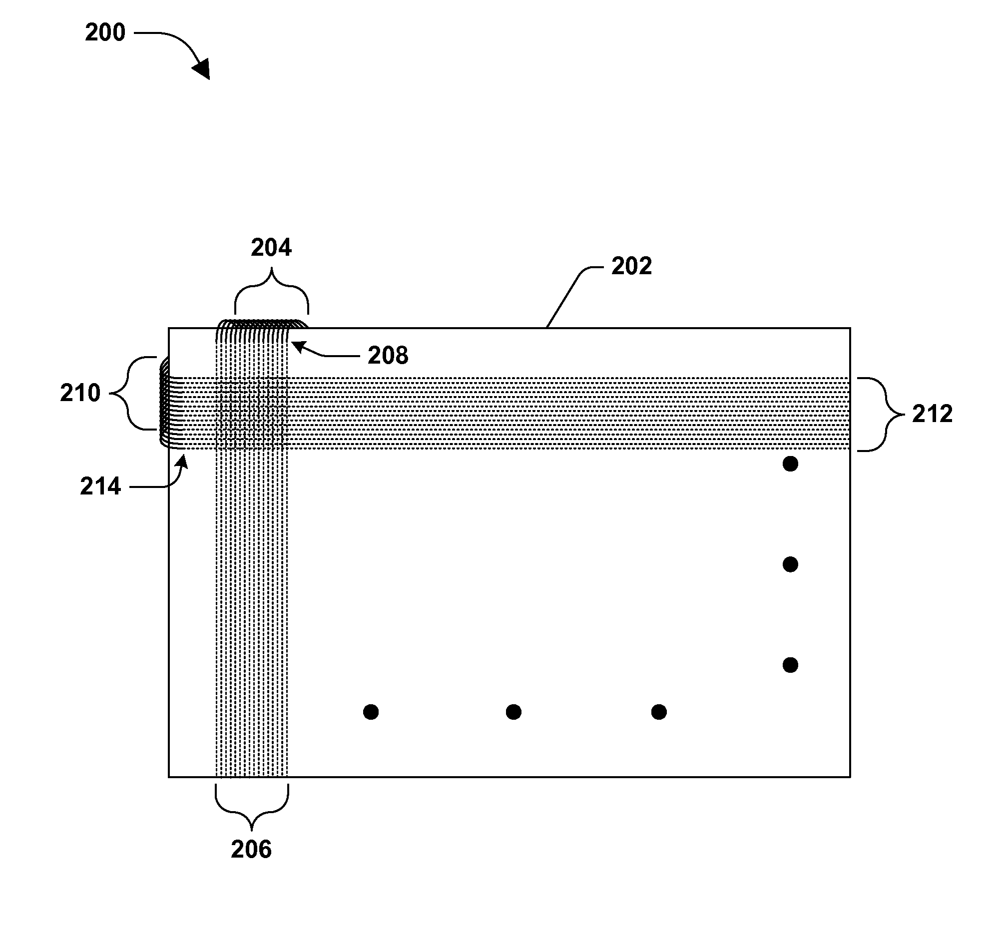
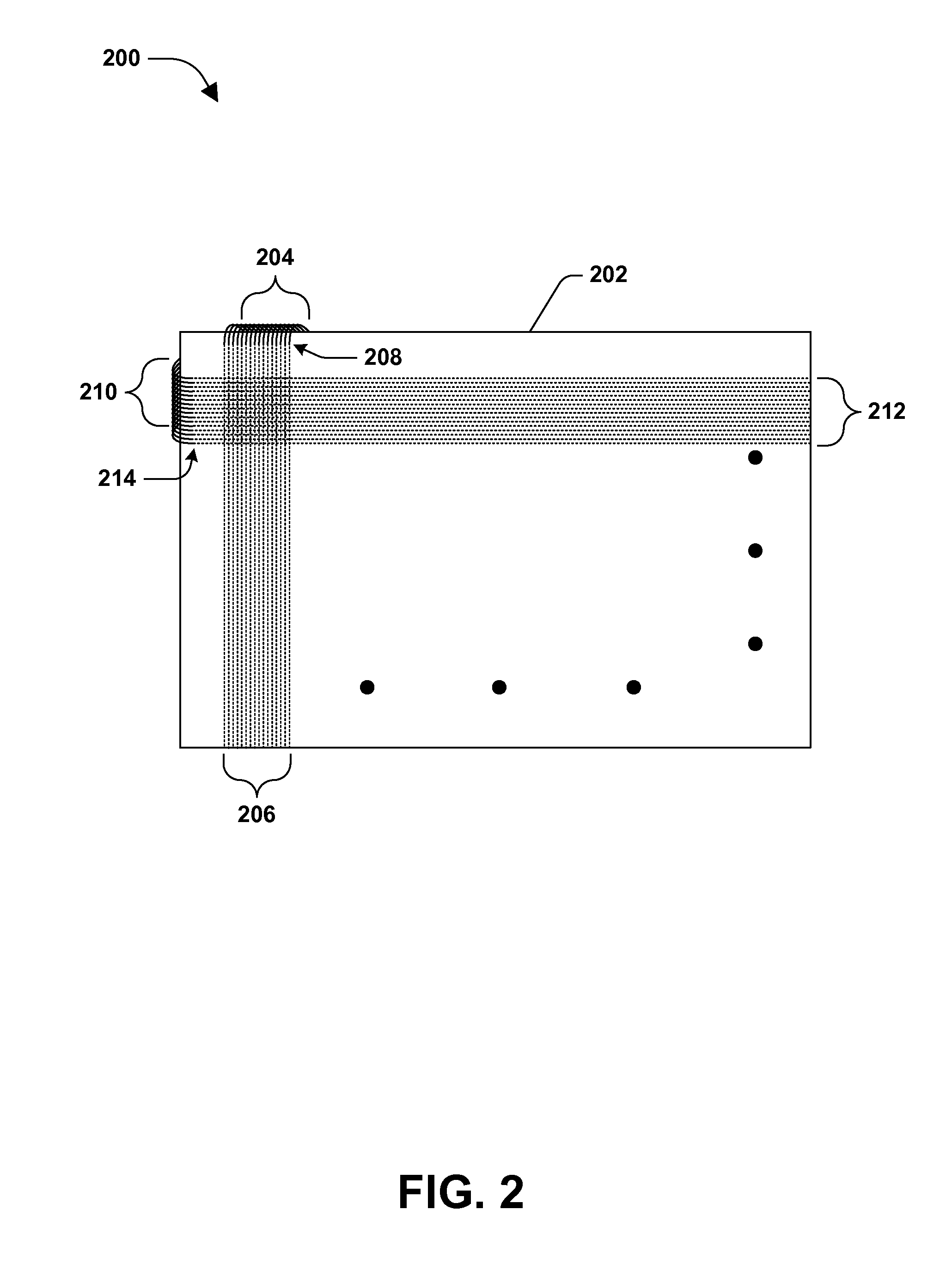
[0023]FIG. 2 is a component diagram illustrating another example embodiment 200 of a conventional LCD system design. A drive-line side face (the inside face) of a rear LCD substrate sheet 202 (e.g., comprising glass or a transparent polymer) is shown. In this embodiment 200, column drive line 206 and row drive lines 212 are shown for illustrative purposes; however, typically these components continue across the drive-line face of the rear LCD substrate sheet 202. Driver connections 204 and 210 are routed from behind the rear LCD substrate sheet 202, around its edge, to the drive-line side face. The driver connections 204 and 210 connect at 208 and 214 to column drive lines 206 and row drive lines 212, respectively. As described above, routing the driver connections around the edge of the rear LCD substrate sheet 202 necessitates a bezel at the respective edges to cover the driver connectors 204 and 210, thus preventing a “full bleed” display.

[0024]An LCD can be devised that mitigate...

embodiment 400

[0031]In this embodiment 400, a light source 422 (e.g., an array of LEDs) is disposed between the drivers 312 and the rearward LCD substrate sheet 304. Further, the light source 422 is disposed entirely within a footprint formed by the rearward LCD substrate sheet 304. For example, as described above, the light source can comprise an array of LEDs controlled by the circuit board 310. The light source 422 may comprise several components that provide for light from the LEDs to be directed toward the LCD and diffused appropriately across the LCD, for example. Additionally, in this embodiment, in order to mitigate a need for a bezel or frame around the LCD, the light source 422 fits entirely within the area of the LCD (e.g., does not extend beyond the edges of the LCD).

[0032]FIGS. 5A and 5B illustrate exemplary embodiments 500 and 550 of one or more portions of an LCD. In the exemplary embodiment 500 of FIG. 5A, the vias comprise a hole 512 formed through the rearward LCD substrate shee...

embodiment 600

[0037]FIG. 6 is a component diagram illustrating another exemplary embodiment 600 of one or more portions of an LCD. In this embodiment 600, the rearward LCD substrate sheet 602 comprises several sets of column vias 604A, 604B, 604C, for example, where the respective display columns comprise three vias (e.g., one of 604A, one of 604B and one of 604C per respective display column). The respective vias 604 are connected to column drive lines 608A, 608B, 608C, for example, where the respective display columns comprise three drive wires (e.g., of shorter length than a full length drive line).

[0038]Further, the rearward LCD substrate sheet 602 comprises several sets of row vias 606A, 606B, 606C, for example, where the respective display rows comprise three vias. The respective vias 606 are connected to row drive lines 610A, 610B, 610C, where the respective display rows comprise three drive wires. In this way, for example, each via can be connected to a driver (e.g., one per driver, one s...


PUM

PropertyMeasurementUnit
Electrical conductoraaaaaaaaaa
Transparencyaaaaaaaaaa
Conductionaaaaaaaaaa

Abstract

A liquid crystal display (LCD) is provided that comprises a rearward LCD substrate sheet that has an array of vias formed, where the vias provide electrical conduction between both sides of the rearward LCD substrate sheet. The number of vias in the array is substantially equal to or at least equivalent to a combination of a number of column drive lines and a number of row drive lines. The respective drive lines are connected to a corresponding via, such as on one side of the rearward LCD substrate sheet, and respective patterned conductors are connected to a corresponding via, such as on the other side of the rearward LCD substrate sheet. The patterned conductors provide a connection between respective drive lines and one or more corresponding drivers. In one example, this allows a “full bleed” display to be generated.

Description

BACKGROUND[0001]A liquid Crystal Display (LCD) is a thin, flat dynamic display that uses liquid crystals (LCs) to modulate light emitted from a light source, typically from a backlighting component. LCDs are widely used in a variety of applications including: televisions, monitors (e.g., computer monitors), device instrument panels (e.g., clocks, games, calculators, and detectors), vehicle displays, telephones, portable media players, signage, etc. They are particularly useful in small consumer electronics, but have also found great commercial success in large display systems. LCDs have displaced cathode ray tube (CRT) displays in most applications, as they are usually more compact, lightweight, portable, and affordable.[0002]To provide a general background, LCDs systems typically comprise a backlighting unit, comprising cold cathode fluorescent lights (CFLs) or light emitting diodes (LEDs), which provide the light for the LCD. The LCD itself often comprises layers of thin film tran...

Claims


Application Information

Patent Timeline
IPC IPC(8): G02F1/1345
CPCG02F1/13452G02F1/13439G02F1/133504G02F1/133603Y10T29/49165G02F2201/42G02F2001/13456G02F2001/133567G02F1/13454G02F1/133567G02F1/13456
Inventor KAJIYA, JAMES T.WHITTED, JOHN TURNER
Owner MICROSOFT TECH LICENSING LLC
Why Eureka
Try Eureka