Load measuring apparatus, method, and program

a technology for measuring apparatus and load, applied in the direction of instruments, electric generator control, force/torque/work measurement apparatus, etc., can solve the problems of enormous work time, calibration work, and calibration work, and achieve the effect of efficient calibration

Active Publication Date: 2012-08-28
MITSUBISHI HEAVY IND LTD
View PDF6 Cites 15 Cited by
  • Summary
  • Abstract
  • Description
  • Claims
  • Application Information

AI Technical Summary

Benefits of technology

[0007]The present invention has been achieved to solve the above problem, and an object thereof is to provide a load measuring apparatus, method, and program capable of efficiently calibrating a load on a wind turbine blade regardless of observation conditions.
[0009]With such a configuration, the calibrating means for calibrating the function held in the load calculating means is provided. The calibrating means calibrates the function based on the measurement data of the sensor obtained in the pitch angle range and the rotational speed range of the wind turbine blade in which the variation between the maximum and minimum aerodynamic torques due to wind speeds is equal to or less than a predetermined value. Therefore, the conditions of the wind speed can be widened.
[0014]Since the load is associated with the azimuth angle and the pitch angle in the table in the calibrating means, when the azimuth angle and the pitch angle upon the measurement data being obtained are known, the load on the wind turbine blade at that time can be easily grasped. Since the parameter of the function is calibrated based on the relation between the distortion of the wind turbine blade calculated based on the measurement data and the load determined based on the measurement data, the distortion of the measurement data can be calibrated with high precision.
[0016]With the configuration, the measurement data in the calm state included in the measurement data of the sensor is obtained and the offset calibration is performed thereon, so that precision of the measurement data can be improved.
[0027]According to the present invention, there is an effect that a load on a wind turbine blade can be efficiently calibrated regardless of observation conditions.

Problems solved by technology

However, the calibration work has to be performed for each wind turbine.
In a case of a large-scaled wind firm in which hundreds of wind turbine generators are installed, enormous work time is necessary.
In addition, since the relation between a load applied to a wind turbine blade and a distortion varies among wind turbines and wind turbine blades, the calibration work has to be repeatedly performed on the wind turbine blades.
It takes long time to move a blade to a predetermined position (angle) by using a turning motor and fix it, and thus the work is not performed smoothly.
There is consequently a problem such that the work efficiency is low.

Method used


Image

  • Load measuring apparatus, method, and program
  • Load measuring apparatus, method, and program
  • Load measuring apparatus, method, and program

Examples


first embodiment

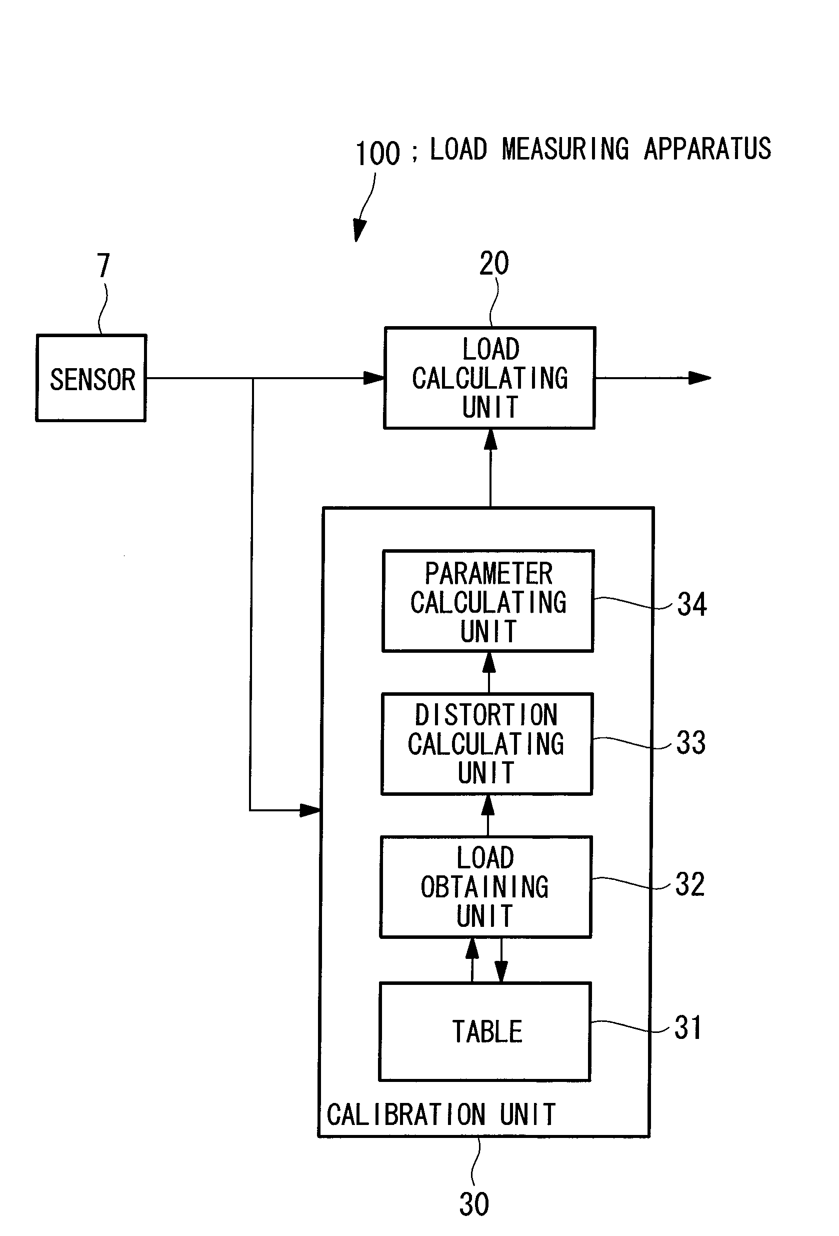
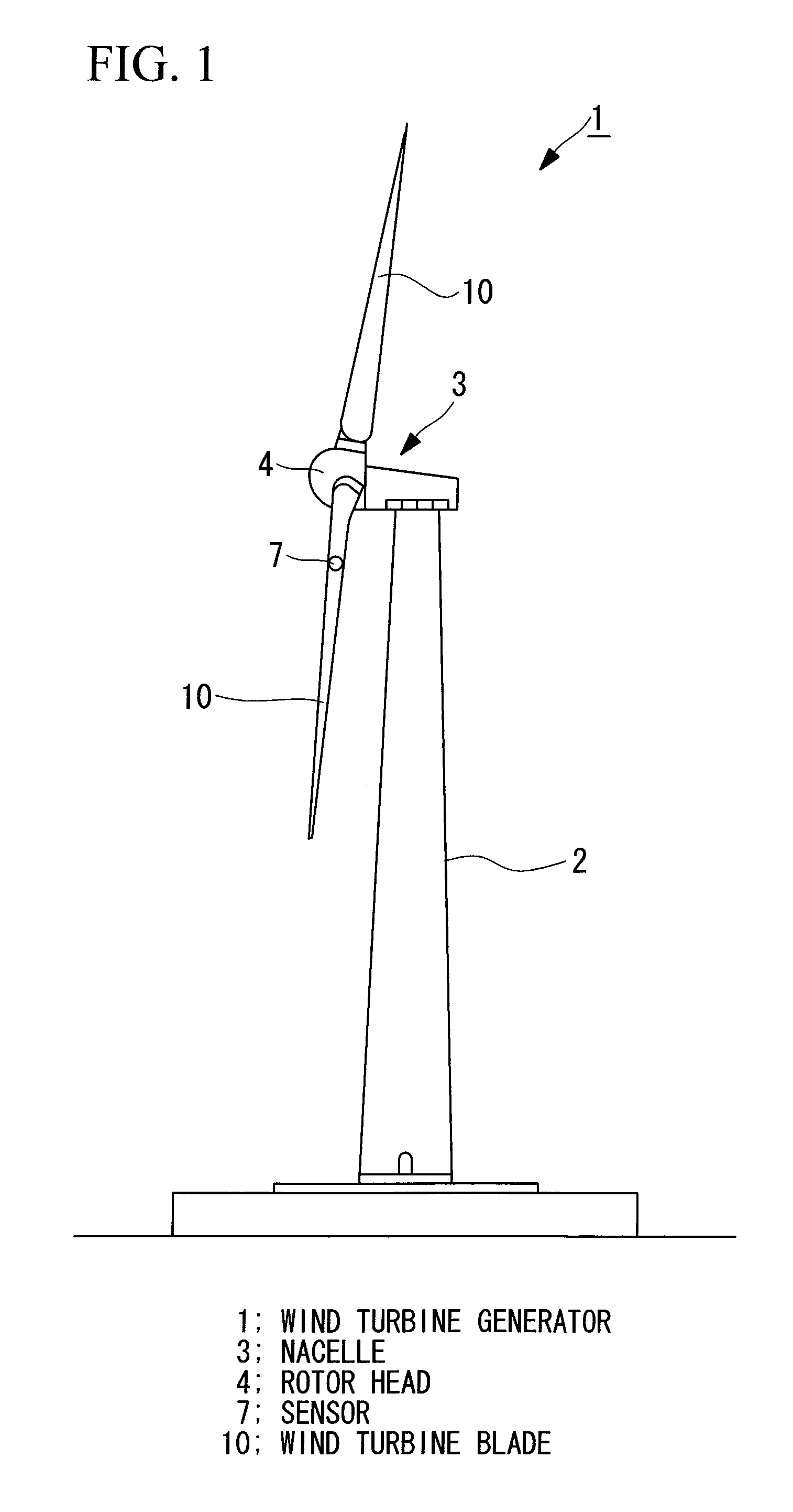
[0053]FIG. 1 is a diagram showing a schematic configuration of a wind turbine generator to which a load measuring apparatus 100 according to the present embodiment is applied. A wind turbine generator 1 according to the present embodiment is a wind turbine in which a pitch angle of a wind turbine blade 10 is variable.

[0054]The wind turbine generator 1 includes, as shown in FIG. 1, a support 2, a nacelle 3 mounted on the upper end of the support 2, and a rotor head (hub) 4 provided to the nacelle 3 so as to be rotatable about an almost horizontal axis. To the rotor head 4, three wind turbine blades 10 are radially attached about the rotational axis of the rotor head 4. With the configuration, the force of wind hitting the wind turbine blade 10 from the rotational axis direction of the rotor head 4 is converted to power for rotating the rotor head 4 about the rotational axis, and this power is converted to electric energy by a generator.

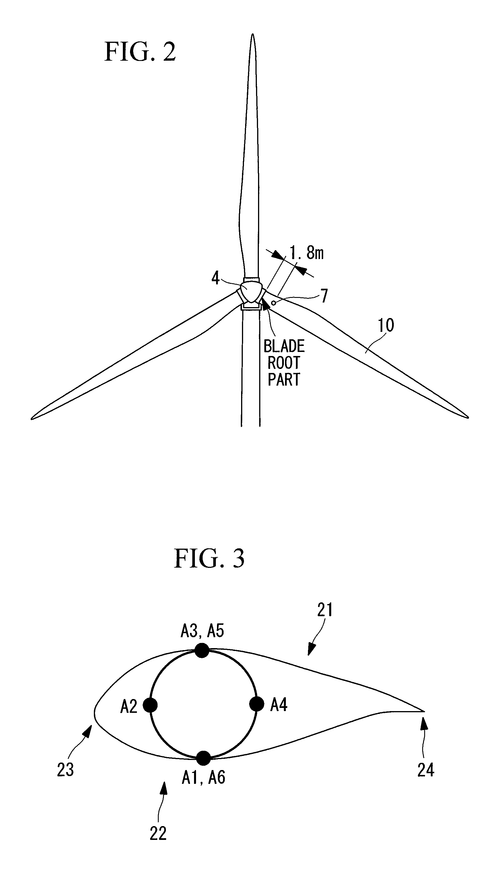
[0055]Each of the wind turbine blades 10 is prov...

second embodiment

[0128]Next, a second embodiment of the present invention will be described.

[0129]The difference in the load measuring apparatus of the present embodiment from the first embodiment is that data is obtained such that angle data of the azimuth angle and the pitch angle is limited to predetermined values and wind speeds are limited to a range in which negative aerodynamic torques are small. In the following, with respect to the load measuring apparatus according to the present embodiment, the points common to the first embodiment will not be described and different points will be mainly described.

[0130]When the wind speed is three meters or less, the sensor 7 obtains measurement data when the pitch angle is set to the minimum and maximum pitch angles at two points of a first azimuth angle and a second azimuth angle turned by 180 degrees from the first azimuth angle.

[0131]More concretely, the sensor obtains measurement data in the case where the wind speed is three meters or less, the az...


PUM


Abstract

A load is based calibrate on data collected under wide observation conditions and promptly calibrate loads of a plurality of wind turbine blades. A load measuring apparatus is applied to a wind turbine in which a pitch angle of a wind turbine blade is variable. The apparatus includes a sensor for obtaining a distortion of the wind turbine blade; a load calculating unit having a function expressing a relation between the distortion of the wind turbine blade and a load on the wind turbine blade, for obtaining the load on the wind turbine blade by applying to the function the distortion based on measurement data of the sensor; and a calibration unit for calibrating the function based on the measurement data of the sensor obtained in a pitch angle range and a rotational speed range of the wind turbine blade in which a variation between maximum and minimum aerodynamic torques is equal to or less than a predetermined value.

Description

CROSS-REFERENCE TO RELATED APPLICATIONS[0001]The present application is based on International Application No. PCT / JP2009 / 058139, filed Apr. 24, 2009, and priority is hereby claimed under 35 USC §119 based on this application. This application is hereby incorporated by reference in its entirety into the present application.TECHNICAL FIELD[0002]The present invention relates to a load measuring apparatus, method, and program.BACKGROUND ART[0003]Generally, in a wind turbine generator, sensors each for measuring a load applied to a wind turbine blade are attached to a blade root part and the like, and a load is calculated by processing data measured by those sensors. However, since the relation between a load applied to each of the wind turbine blades and a distortion is not constant due to individual differences which occur at the time of manufacture of blades and at the time of attachment of the sensors, there is proposed a method of measuring a load for each wind turbine blade and ca...

Claims


Application Information

Patent Timeline
Patent Type & Authority Patents(United States)
IPC IPC(8): G06F19/00F03D7/04H02P9/04
CPCF03D11/0091F05B2260/83F05B2270/802F05B2270/808Y02E10/721F05B2270/331Y02E10/722F03D17/00Y02E10/72F05B2270/328
Inventor FUJIOKA, HIDEYASUHAYASHI, YOSHIYUKI
Owner MITSUBISHI HEAVY IND LTD
Why Eureka
Try Eureka