Method for operating a spindle of a two-for-one twister or cabling machine

a technology of cabling machine and spindle, which is applied in the direction of yarn, continuous wound-up machine, textiles and paper, etc., can solve the problems of affecting the height of the balloon, the reduction of the rotational speed of the spindle is accompanied by a loss of productivity, and the influence of the possibility by means of the parameters mentioned, so as to reduce the energy consumption

Active Publication Date: 2012-09-04
ZHUOLANG INTELLIGENT MACHINERY CO LTD
View PDF13 Cites 13 Cited by
  • Summary
  • Abstract
  • Description
  • Claims
  • Application Information

AI Technical Summary

Benefits of technology

[0007]The invention is based on the object of providing a method for operating a two-for-one twister or cabling machine, which is distinguished by reduced energy consumption, and proposing a two-for-one twister or cabling machine to carry out the method.
[0011]According to the present method, it is proposed that the feed speed of the yarn is adjusted in such a way that no storage is adjusted and that the yarn tension adopts a value which minimizes the diameter of the free yarn balloon encompassing the spindle as a function of the geometry of the spindle. The value of the yarn tension is adjusted according to the method of the invention in such a way that the yarn tension being adjusted becomes greater than the yarn tension adjusting itself during the use of a storage disc or due to the forced guidance of the yarn balloon in a pot. The principle, that the free yarn balloon has a pronounced, incontrovertible geometry, is breached by the method according to the invention, so that it needs no storage as in German Patent Publication DE 41 21 913 A1 or no forced guidance by a pot according to European Patent Publication EP 1 167 597 B1, which have the required compensating function in the twisting or cabling system. The increased yarn tension before entering the guide device leads to the fact that a different ejection angle is adjusted at the edge of the twisted yarn plate because of the reduced balloon diameter from the ejection angle, which is adjusted in the case of a tangential lifting of the yarn from a conventional spindle with a storage disc with the formation of a free yarn balloon or in the yarn balloon which is force-guided by the pot, which has the compensating function of the storage disc in a free yarn balloon. As the drive power is directly dependent on the balloon diameter, the reduction in the diameter of the free yarn balloon leads to the fact that the energy to be applied to form and maintain the rotation of the yarn balloon drops, so a saving in the energy consumption at the spindle of 20% to 30% can be achieved.
[0012]In this case, the yarn requirement at the twist or cabling point should be constantly determined and the feed speed of the yarn adapted to the determined yarn requirement. By continuously adapting the feed speed, fluctuations in the supply of the yarn, which can lead to a break of the yarn or to a collapse of the yarn balloon, are avoided.
[0018]The two-for-one twister or cabling machine is proposed to carry out the method, characterized in that a controllable or regulatable device is connected upstream of the twisted yarn plate to influence the yarn tension, by means of which device the feed speed of the yarn is adjusted in such a way that the yarn tension of the yarn entering the feed device adopts a value which minimizes the diameter of the free yarn balloon encompassing the spindle as a function of the geometry of the spindle. The yarn fed to the feed device is loaded by the controllable or regulatable device connected upstream of the spindle drive to influence the yarn tension with a yarn tension in order to minimize the free yarn balloon being formed, which has a direct positive influence on the energy consumption of the spindle drive.

Problems solved by technology

This is disadvantageous in that the balloon shape decisively also determines the energy consumption at each spindle but the influencing possibilities by means of the parameters mentioned are very small.
Thus a reduction in the rotational speed of the spindle is accompanied by a loss in productivity.
It is only possible to influence the balloon height to a limited extent as components on the textile machine arranged further on in the yarn course limit the design scope.
The free residual yarn balloon forming above the pot between the edge thereof and the yarn guide eyelet is not suitable to separate the yarn tension before and after the spindle in order to compensate influences in the supply.
It proves to be disadvantageous in the cabling device known from European Patent Publication EP 1 167 597 B1 that the use of the pot which is subject to not inconsiderable wear owing to the rotating outer yarn, has to also be moved as a rotating mass by the spindle drive.
In addition, the air friction of the pot causes additional losses that have to be compensated by the spindle drive.

Method used


Image

  • Method for operating a spindle of a two-for-one twister or cabling machine
  • Method for operating a spindle of a two-for-one twister or cabling machine
  • Method for operating a spindle of a two-for-one twister or cabling machine

Examples


Embodiment Construction

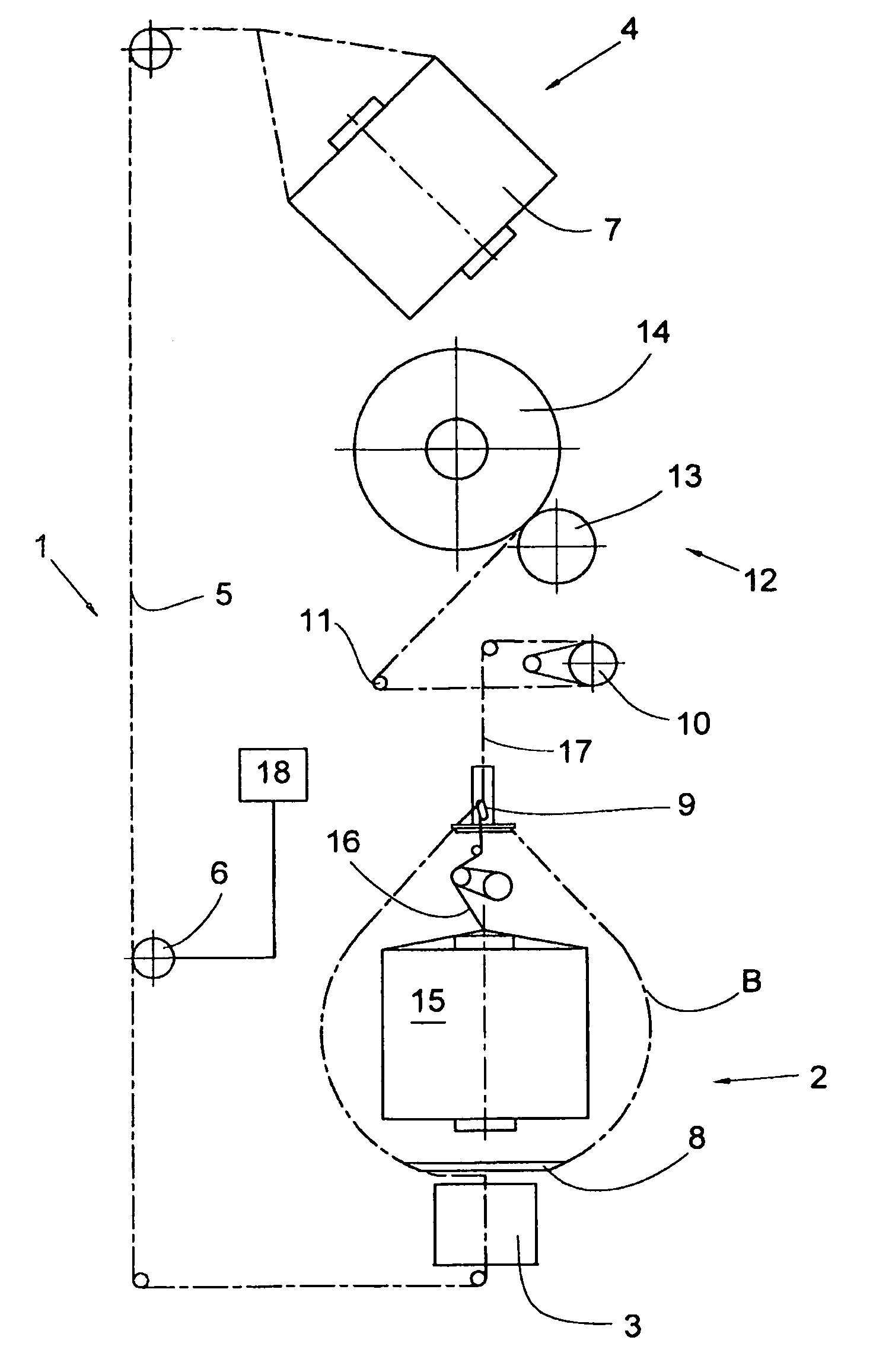
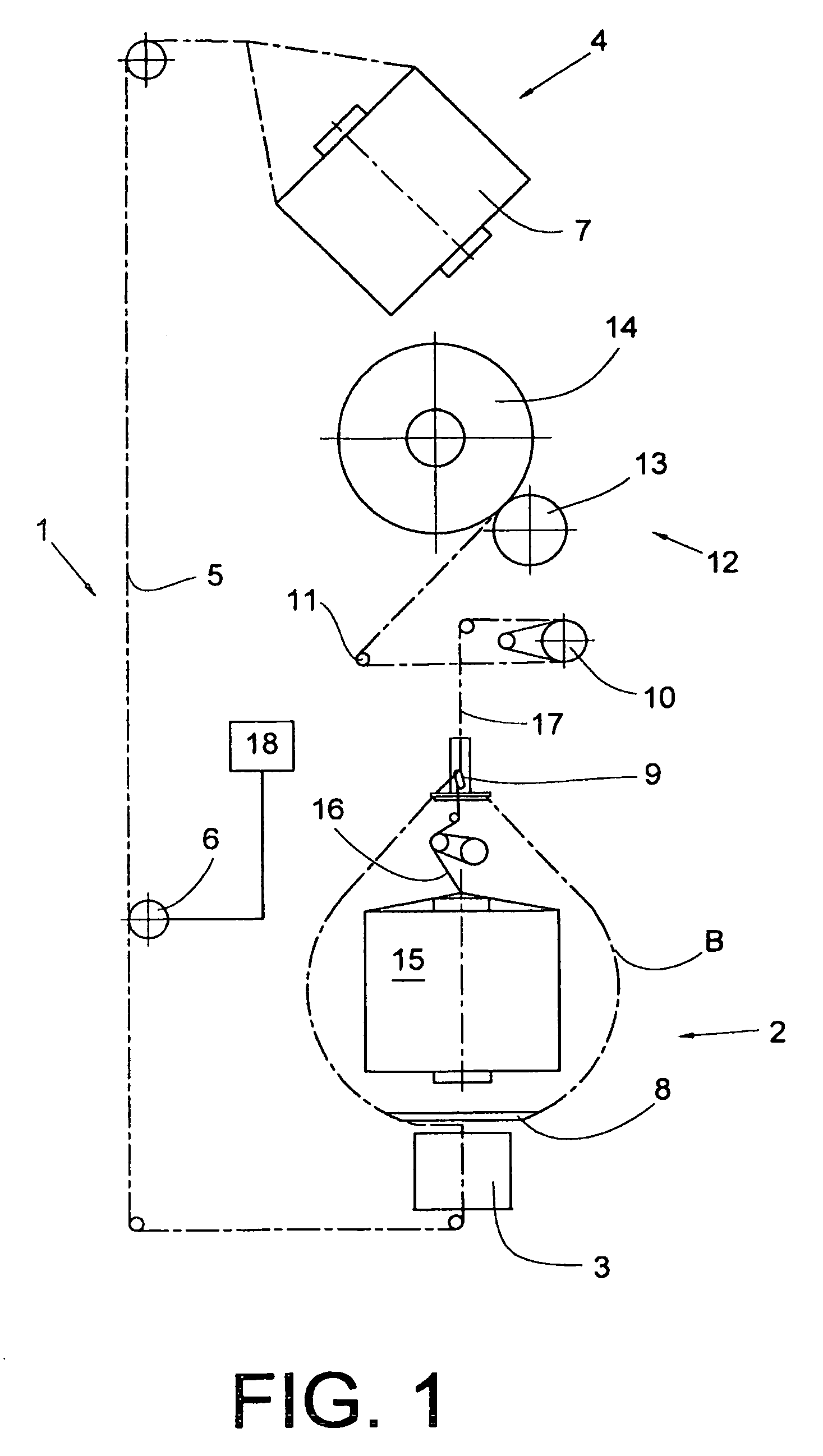
[0026]FIG. 1 shows a schematic view of the structure of a workstation 1 of a cabling machine, with the aid of which the method according to the invention is described. The workstation 1 has a creel 4, which is used to receive at least a first supply bobbin 7, from which a so-called outer yarn 5 is drawn. Furthermore, the workstation 1 comprises a cabling spindle 2, which is driven by a spindle drive 3. The spindle drive 3 may be a motor which directly drives the cabling spindle 2 or an indirect drive, for example a belt drive. The cabling spindle 2 carries, on a twisted yarn plate 8 arranged on the cabling spindle 2, a second supply bobbin 15, from which a so-called inner yarn 16 is withdrawn overhead, which is supplied above the cabling spindle 2 to a balloon eyelet or a compensation system 9, in the present embodiment, a cord regulator.

[0027]The outer yarn 5 withdrawn from the first supply bobbin 7 is fed to a regulatable yarn tension influencing device 6 arranged between the cree...


PUM

PropertyMeasurementUnit
diameteraaaaaaaaaa
speedaaaaaaaaaa
tensionaaaaaaaaaa

Abstract

A two-for-one twister or cabling machine and a method for operation thereof, wherein a yarn (5, 25) is withdrawn from a supply bobbin (7, 21) and fed to a guide device below a twisted yarn plate (8, 24) of the spindle (2, 22) and from which the yarn (5, 25) exits virtually perpendicular to the axis of the spindle (2, 22) and is deflected to the outer edge of the twisted yarn plate (8, 24) and runs along the spindle (2, 22) as a free yarn balloon (B) encompassing the spindle (2, 22), until the yarn (5, 25) is fed into the twist or cabling point of a yarn guide device (9, 27) above the spindle (2, 22). The supply speed of the yarn (5, 25) is adjusted to achieve a yarn tension which minimizes the yarn balloon diameter as a function of the spindle geometry.

Description

CROSS-REFERENCE TO RELATED APPLICATIONS[0001]This application claims the benefit of German patent application 10 2008 033 849.4, filed Jul. 19, 2008, and corresponding Patent Cooperation Treaty Application No. PCT / EP2009 / 003760, filed May 27, 2009, each herein incorporated by reference.BACKGROUND OF THE INVENTION[0002]The present invention relates to a method for operating a spindle of a two-for-one twister or cabling machine and a two-for-one twister or cabling machine for accomplishing such method.[0003]It is known from German Patent Publication DE 41 21 913 A1 to influence the yarn tension of an inner yarn and an outer yarn on a cording spindle by means of adjusting mechanisms in such a way that the yarns are guided together at the cabling point at the same yarn tension and speed. In this case, the outer yarn is influenced by an outer yarn brake, the braking effect of which is controlled as a function of an inner yarn brake influencing the inner yarn. The outer yarn is introduced...

Claims


Application Information

Patent Timeline
Patent Type & Authority Patents(United States)
IPC IPC(8): D01H1/10
CPCD01H1/10D02G3/285D01H13/108D01H7/86D01H13/102D01H13/32
Inventor SCHLAGENHAFT, WALTER
Owner ZHUOLANG INTELLIGENT MACHINERY CO LTD
Why Eureka
Try Eureka