Eureka AIR delivers breakthrough ideas for toughest innovation challenges, trusted by R&D personnel around the world.

Integrated hypersonic inlet design

a hypersonic inlet and design technology, applied in the direction of machines/engines, aircraft navigation control, transportation and packaging, etc., can solve the problems of reducing engine performance, reducing engine efficiency, and affecting the shape of the inlet for scramjets or other propulsion, so as to improve the efficiency of the aircraft

Active Publication Date: 2012-09-04
THE BOEING CO
View PDF8 Cites 74 Cited by
  • Summary
  • Abstract
  • Description
  • Claims
  • Application Information

AI Technical Summary

Benefits of technology

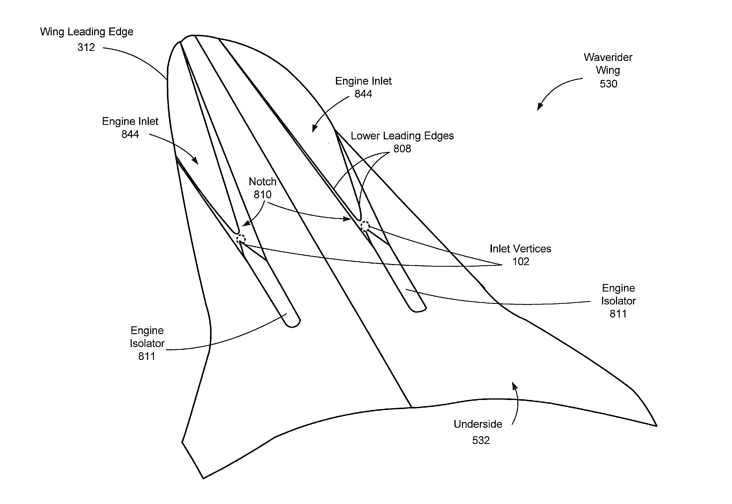
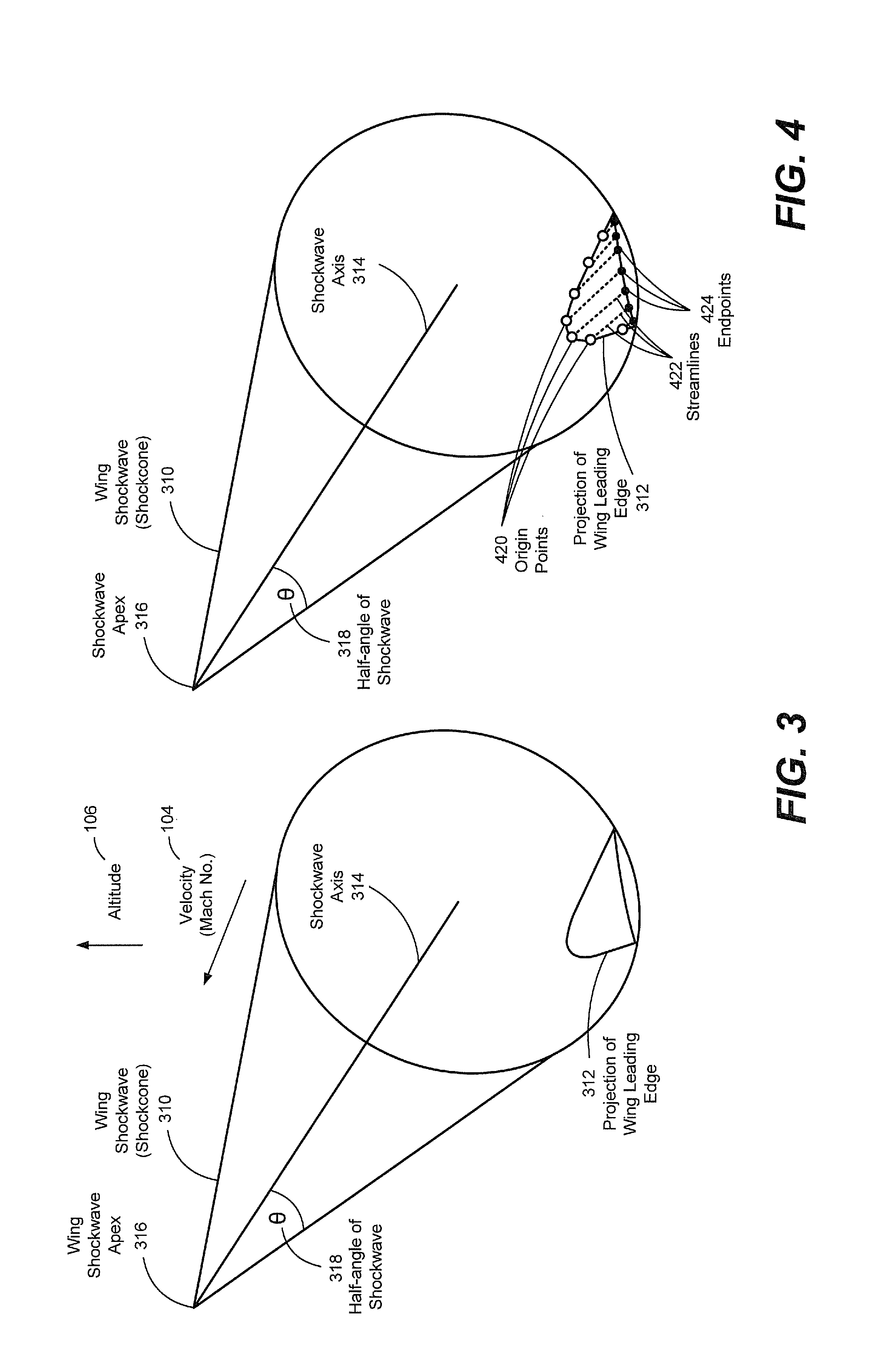
[0005]Embodiments disclosed herein include aircraft, aircraft bodies, and methods for designing a shape of an engine inlet on a waverider wing of a hypersonic aircraft. Both a waverider wing of a hypersonic aircraft and engine inlets formed on the waverider wing generate shockwaves at hypersonic speeds. The shockwaves may be cones and can be represented as more general shapes but for simplicity they will hereafter be referred to as cones. A generating shockwave of a waverider wing, which will be referred to as a “wing shockwave,” has an apex forward of the aircraft and widens as the generating shockwave nears a surface of the waverider wing where the shockwave may contact an edge of the waverider wing. An inlet shockwave of each engine inlet may have an apex behind an aperture to the engine that widens as it moves forward of the aircraft. When the engine inlet is shaped so that lower leading edge of the engine inlet lies at the intersection of the generating wing shockwave and the generating inlet shockwaves, the waverider wing and the engine inlets all ride on the wing shockwave, which may improve the efficiency of the aircraft.
[0009]By positioning leading edges of the engine inlets on the generating wing shockwave, the engine inlets can perform without altering the shockwave of the aircraft. By using three-dimensional engine inlets, engine performance may be improved for a given planform for a hypersonic vehicle.

Problems solved by technology

In traveling at such high speeds, pressure from impacted air molecules may build up in front of aircraft forward-facing surfaces, resulting in a shockwave.
Another issue in the design of hypersonic aircraft is the shape of inlets for scramjets or other propulsion devices that use ambient air (as opposed to rocket engines or other self-contained propulsion devices).
However, two dimensional inlets may not be as efficient as three dimensional inlets at hypersonic speeds.
A resulting standing shockwave in front of the engine inlet may cause air to spill from the engine inlet that cannot be contained by the isolator 1504, reducing engine performance.)

Method used


Image

  • Integrated hypersonic inlet design
  • Integrated hypersonic inlet design
  • Integrated hypersonic inlet design

Examples


Embodiment Construction

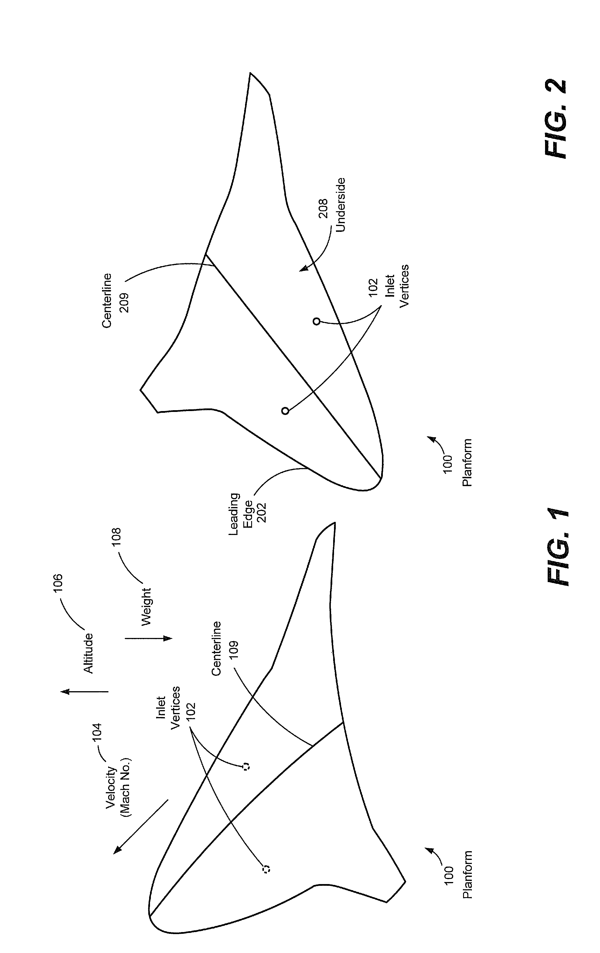
[0031]Methods, aircraft, and engine nacelles are disclosed in accordance with particular embodiments of integrated hypersonic inlet design. According to a particular illustrative embodiment, a waverider wing may be formed from a planform with engine inlets integrated therewith to form a hypersonic aircraft. The waverider wing and the engine inlets may ride on a wing shockwave of the waverider wing during operation. According to another particular embodiment, given an existing planform, one or more engine inlets and engine nacelles may be designed for the waverider wing to enable the waverider wing and the engine inlets to ride on the wing shockwave. A shape of the engine inlets may be shaped by determining points of intersection of the wing shockwave and one or more inlet shockwaves produced by the engine inlets. Streamline tracing may be used to form an inner shape of the engine inlets between a leading edge of each engine inlet and an intake of the associated engine. Streamline tr...


PUM


Abstract

Methods, aircraft, and engine nacelles are disclosed. A wing leading edge of a planform is superimposed on a wing shockwave that extends in a first direction from a shockwave apex toward the wing leading edge. A waverider shape is streamline traced between the wing leading edge and a trailing edge of the planform to form a waverider wing. A position of an engine inlet vertex relative to the waverider wing is identified. An inlet shockwave is projected from the inlet vertex in a second direction generally opposed to the first direction. The inlet shockwave intersects the wing shockwave. An inlet leading edge of an engine inlet includes a lower leading edge including a plurality of points where the inlet shockwave intersects the wing shockwave.

Description

FIELD OF THE DISCLOSURE[0001]The present disclosure is generally related to designing a shape of an engine inlet on a waverider wing of a hypersonic aircraft.BACKGROUND[0002]For aircraft designed for hypersonic travel (i.e., travel at several times the speed of sound), the shape of the aircraft body is very important. In traveling at such high speeds, pressure from impacted air molecules may build up in front of aircraft forward-facing surfaces, resulting in a shockwave.[0003]For the sake of aerodynamic efficiency, wings of some hypersonic aircraft are designed to ride on this shockwave. The shockwave forms a region of pressurized air behind it under the aircraft. The shockwave is a very thin surface in the air that trails from the wing leading edge aft and it dissipates behind the vehicle. To ride the shockwave, the leading edge of the aircraft should be sharp and have a combination of sweep and deflection angles small enough to permit a shockwave to remain attached on the leading ...

Claims


Application Information

Patent Timeline
Patent Type & Authority Patents(United States)
IPC IPC(8): B64D33/02
CPCB64D33/02B64D2033/026Y10T137/0536
Inventor SMITH, THOMAS R.BOWCUTT, KEVIN G.
Owner THE BOEING CO
Why Eureka
Eureka Blog
Learn More