Spin nock

a spinner and arrow technology, applied in the field of spinners, can solve the problems of increasing air resistance and producing drag, and achieve the effect of promoting stabilization and reducing drag on the arrow

Inactive Publication Date: 2012-09-04
HARDING MARTIN DALE
View PDF5 Cites 37 Cited by
  • Summary
  • Abstract
  • Description
  • Claims
  • Application Information

AI Technical Summary

Benefits of technology

[0013]It would be desirable to reduce the drag upon the fletching of an arrow during the initial acceleration phase of an arrow's release and from that time immediately after the initial acceleration phase when the arrow separates from the bow string until the fletching is able to adequately rotate the shaft.
[0015]It would be desirable to increase the stability of an in-flight arrow.
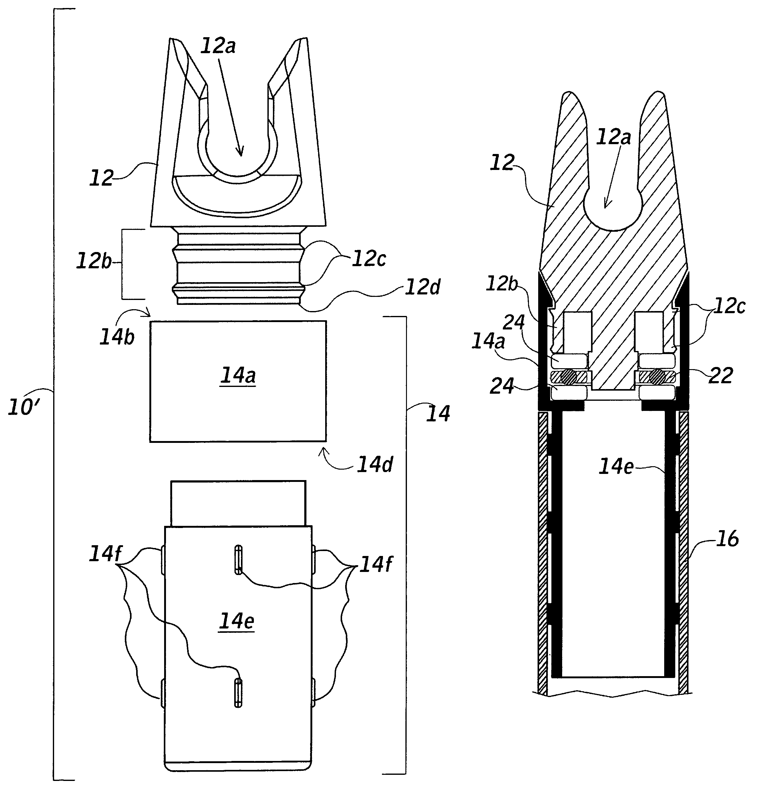
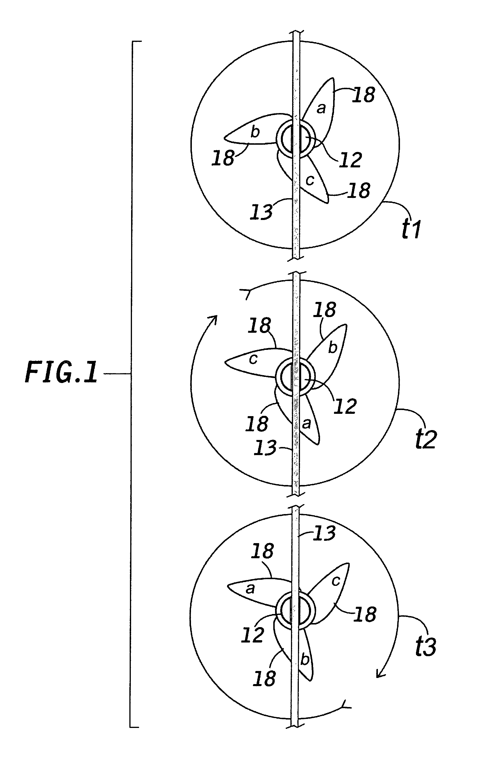
[0021]In either aspect, the nock 12 can freewheel independently of the retainer 14 having spacing means both aligning the nock coaxially with the arrow shaft and separating the nock base from the retainer. The spacing means can be ribbing 12c on the outer surface of the nock base having a low coefficient of friction, or ribbing combined with a thrust bearing 22 residing between the nock base 12b and the retainer. Because the nock freewheels, the arrow shaft 16 is permitted to begin rotation even prior to separating from the bowstring because the bowstring, while supplying forward momentum, can no longer impede the natural rotation of the shaft produced by the vanes or fletching 18 moving through the air. The result is a spinning force upon the shaft consistent with the shaft velocity, vane configuration and wind resistance, causing the entire arrow to begin its spin earlier than what is possible with previous devices.
[0022]The result of the foregoing construction and according to the present invention, is a nock that allows the shaft to spin freely prior to exiting the bow so that the vanes may assume a natural spin upon release which reduces drag upon the arrow while promoting stabilization. Essentially, the present invention allows spin to naturally occur, rather than actively applying the force to the arrow by torquing or other means.

Problems solved by technology

A conventional nock (1) robs the arrow of energy by immobilizing the arrow shaft and accelerating non-spinning fletching forward causing increased air resistance producing drag on the arrow, and (2) interferes with early stabilization that would occur at the onset of release if the arrow were somehow permitted to begin spinning upon release.

Method used


Image

  • Spin nock
  • Spin nock
  • Spin nock

Examples


Embodiment Construction

Reference Listing

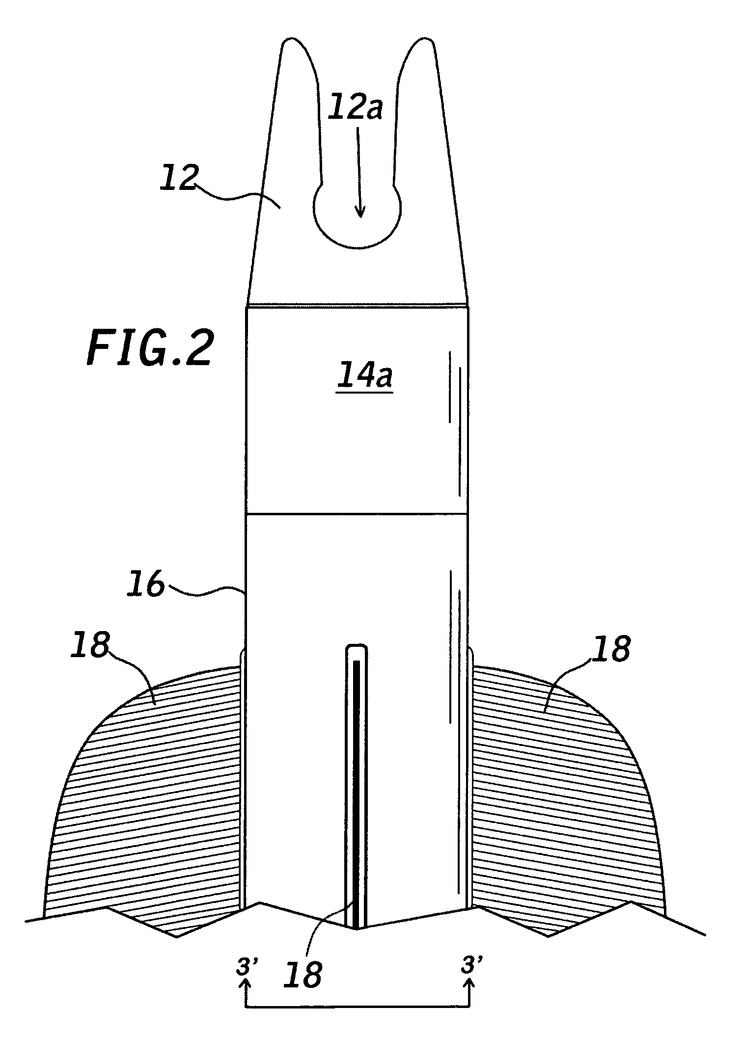
[0034]10′ nock assembly[0035]12 nock[0036]12a bowstring rest[0037]12b nock base[0038]12c nock spacers[0039]12d nock bottom[0040]13 bow string[0041]14 retainer assembly[0042]14a collar[0043]14b upper annulus[0044]14c lip[0045]14d lower annulus[0046]14e bottom portion retainer[0047]14f tabs[0048]16 arrow shaft[0049]18 fletching[0050]22 thrust bearing[0051]24 spacers

[0052]Referring generally to FIGS. 1-10; a preferred embodiment according to the present invention is shown which includes a nock segment 12 with a bowstring rest 12a, a base portion 12b with a series of concentric ridges 12c serving as an alignment and spacing means for the nock segment, a retainer assembly 14, including a collar 14a portion possessing an upper annulus 14b and an lower annulus 14d, and a cylindrical retainer bottom 14e with an upper portion of reduced diameter for fitting inside the collar 14a and a bottom portion for fitting into one end of an arrow shaft 16. The collar 14a has a circumja...


PUM

PropertyMeasurementUnit
diameteraaaaaaaaaa
energyaaaaaaaaaa
potential energyaaaaaaaaaa

Abstract

A nock for promoting a natural spin on an arrow shaft prior to the nock separating from a bowstring includes a nock segment possessing a bowstring rest portion, and a base portion which is coupled to a retaining portion which is attached to the end of an arrow shaft. The nock segment freewheels independently of the retainer and the arrow shaft to permit the fletching moving through the air to act on the shaft producing a natural spin to the shaft prior to its release from the bow.

Description

CROSS REFERENCE TO RELATED APPLICATIONS[0001]This Application claims the benefit of Provisional Patent Application No. 61 / 341,885 filed Apr. 6, 2010, and Provisional Patent Application No. 61 / 403,904 filed Sep. 23, 2010.STATEMENT REGARDING FEDERALLY SPONSORED RESEARCH OR DEVELOPMENT[0002]Not applicableTHE NAMES OF THE PARTIES TO A JOINT RESEARCH AGREEMENT[0003]Not applicableINCORPORATION-BY-REFERENCE OF MATERIAL SUBMITTED ON A COMPACT DISC[0004]Not applicableBACKGROUND OF THE INVENTION[0005]A bow is a simple machine in which the limbs define a two-arm spring. The energy stored by the archer is in form of the drawn stressed bow. The potential energy is then transferred to the arrow in the form of kinetic energy when the archer releases the bowstring permitting the bow limbs to spring forward.[0006]An arrow consists of a tip which may be a target point type or a broadhead type which is affixed to one end of a shaft which may be composed of wood, fiberglass, metal or other suitable mat...

Claims


Application Information

Patent Timeline
Patent Type & Authority Patents(United States)
IPC IPC(8): F42B6/06
CPCF42B6/06F42B10/26Y10T29/49826
Inventor HARDING, MARTIN DALE
Owner HARDING MARTIN DALE
Why Eureka
Try Eureka