
Physical and chemical integrated flow imaging device

a flow imaging and integrated technology, applied in the field of environmental sensors, can solve the problems of insufficient adaptability of the next-generation data carrier, insufficient type of monitored information, etc., and achieve the effect of low yield

Inactive Publication Date: 2012-09-04
UNIV OF SOUTH FLORIDA
View PDF21 Cites 15 Cited by
  • Summary
  • Abstract
  • Description
  • Claims
  • Application Information

AI Technical Summary

Benefits of technology

[0010]In some embodiments, an image sensor is used to convert an optical image focused on the sensor into electrical signals. The image sensor typically includes an array of light detecting elements, where each element produces a signal corresponding to the intensity of light impinging on that element when an image is focused on the array. These signals may then be used, for example, to display a corresponding image on a monitor or otherwise used to provide information about the optical image. Exemplary image sensors include charge coupled device (CCD) and (CMOS). Integrated circuit chips containing a CCD image sensor have a relatively low yield and are expensive due to the specialized processing involved.

Problems solved by technology

However, the present logistics system is not enough to adapt the next generation data carrier.
So far, this type of monitored information has not been available, unless using specially made expensive and large sized device.

Method used


Image

  • Physical and chemical integrated flow imaging device
  • Physical and chemical integrated flow imaging device
  • Physical and chemical integrated flow imaging device

Examples


Embodiment Construction

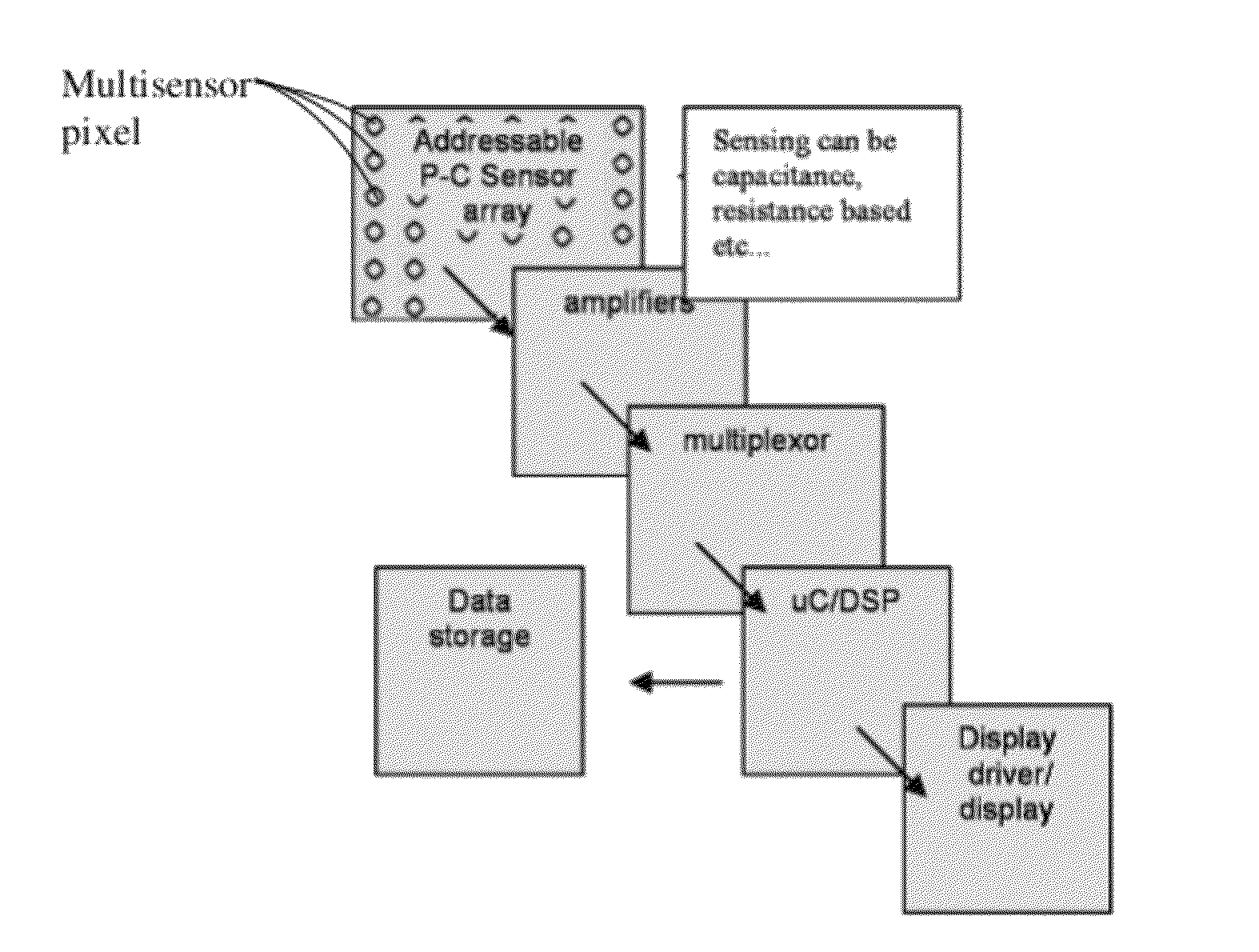
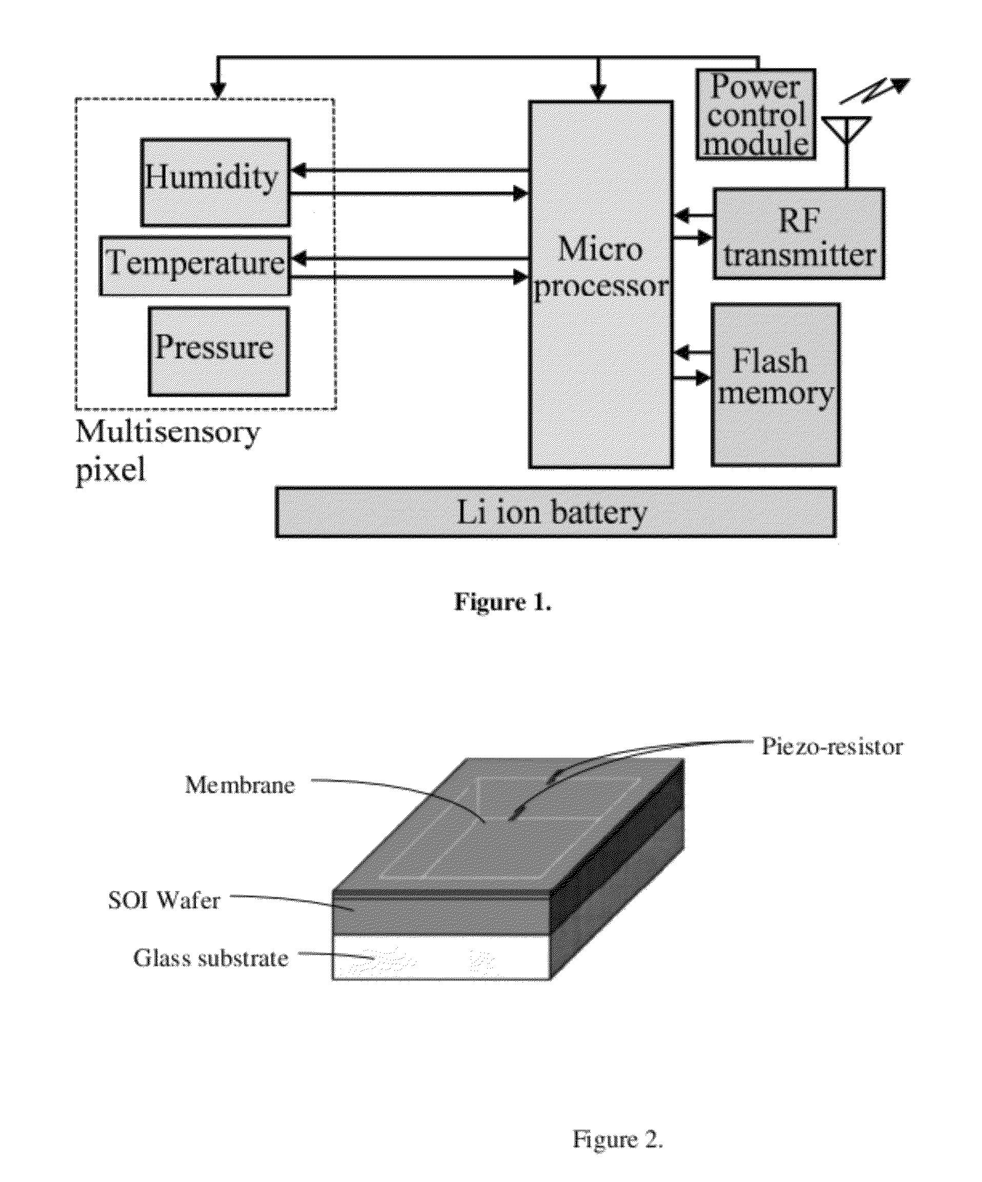
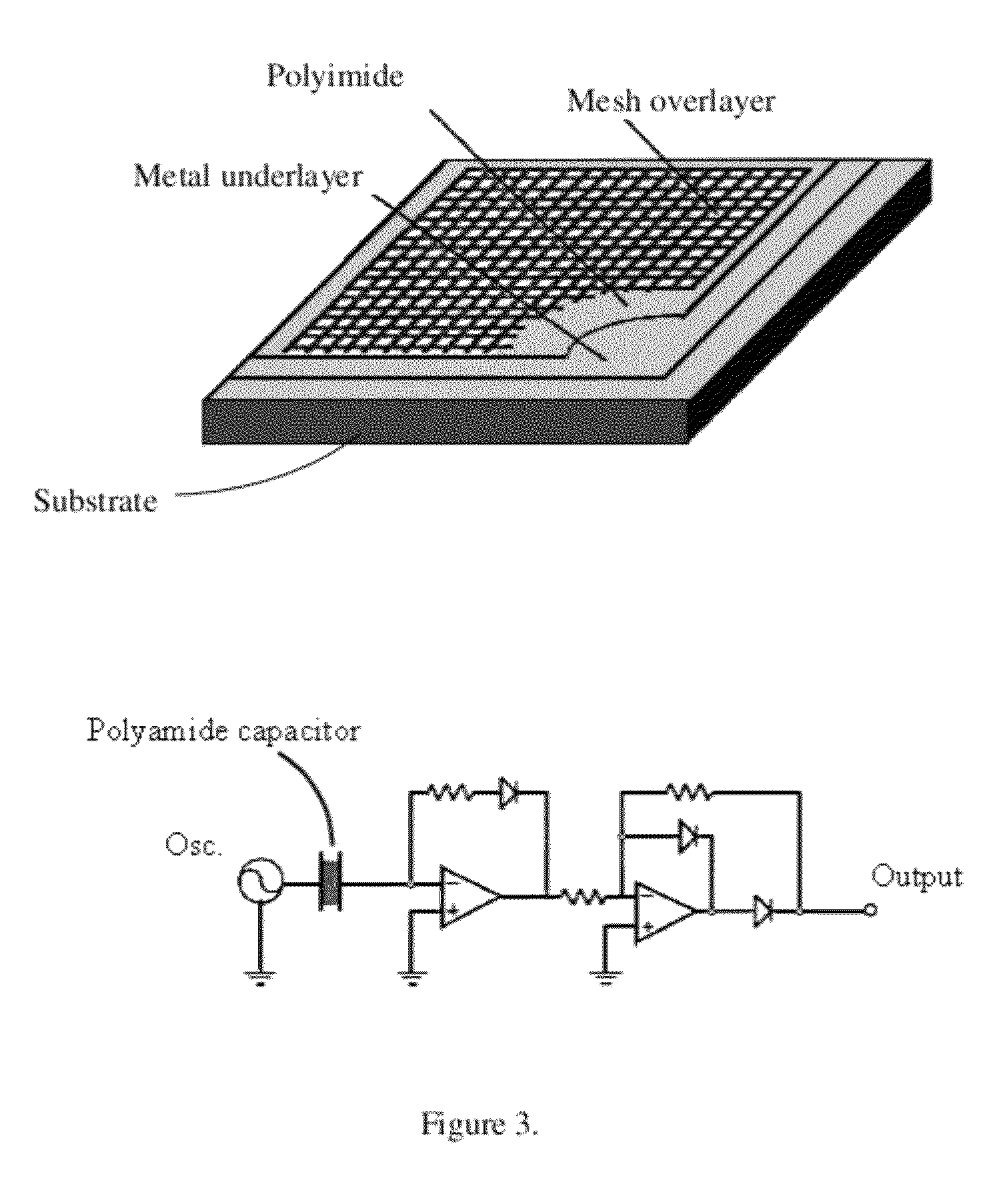
[0027]Disclosed herein is a multi-environmental data monitoring system. Capacitive sensors may be utilized in the device, as these sensors offer high sensitivity yet consume no power and can be read out rapidly using low-power circuit techniques. The system may provide physical sensing for local environmental conditions, including, without limiting the scope of the invention, temperature, pressure microbalance, force, humidity, acceleration; and chemical sensing. Useful chemical sensor may comprise electrochemical, ion selective electrode, ion detector, polymer sensors, chemical field-effect transistor (chemFETs), chemical sensitive membranes, antibody, luminescent reaction chemistries, surface Plasmon elements, regenerate reactive / sense surfaces, discrete sensor chips, and any combination thereof. In some embodiments, the interface circuitry is designed to operate with low power consumption. The multi-environmental sensory device uses an array of MEMS sensors fused into multisensor...


PUM

PropertyMeasurementUnit
power consumptionaaaaaaaaaa
supply currentaaaaaaaaaa
thicknessaaaaaaaaaa

Abstract

The device allows imaging of the flow of proximity multi environmental parameters, like temperature, pressure, force, while simultaneously detecting environmental molecules / chemicals. The device may be housed in a portable camera-like or sheet detection system. Such a system will allow the real time visualization of the chemistry and physics of fluids (air, water, plasmas) in a camera format and create a novel environmental monitoring system.

Description

CROSS REFERENCE TO RELATED APPLICATIONS[0001]This application is a continuation of U.S. application Ser. No. 12 / 492,789, entitled “Physical and Chemical Integrated Flow Imaging Device”, filed Jun. 26, 2009, which claims priority to claims priority to U.S. Provisional Patent Application 61 / 075,803, entitled “Physical and Chemical Integrated Flow Imaging System”, filed Jun. 26, 2008, the contents of which are herein incorporated by reference.FIELD OF INVENTION[0002]This invention relates to environmental sensors. Specifically, the invention discloses multiparameter pixel sensor devices for environmental testing and / or analysis.BACKGROUND OF THE INVENTION[0003]Recently, sensing of the various condition of the given environment is very important technology for the numerous fields (A. Mason, et al., A generic multi-element microsystem for portable wireless applications”, Proc. IEEE 86 (1998) 8). Many applications of the miniaturized environmental-multi-sensor with data logging / transfer s...

Claims


Application Information

Patent Timeline
Patent Type & Authority Patents(United States)
IPC IPC(8): H01L29/66G01N27/00
CPCG01N21/6454G01N21/05G01N21/554G01N21/6428
Inventor FRIES, DAVID
Owner UNIV OF SOUTH FLORIDA
Features
  • Generate Ideas
  • Intellectual Property
  • Life Sciences
  • Materials
  • Tech Scout
  • Unparalleled Data Quality
  • Higher Quality Content
  • 60% Fewer Hallucinations
Learn More