
Method and device for measuring optical characteristic variables of transparent, scattering measurement objects

a technology of optical characteristic variables and measurement objects, applied in measurement devices, optical radiation measurement, instruments, etc., can solve the problem of not being able to perform haze measurement in inline coating apparatuses for quality assurance, and achieve the effect of eliminating the non-linearity of measurement channels

Inactive Publication Date: 2012-09-04
VON ARDENNE ANLAGENTECHNIK GMBH
View PDF14 Cites 14 Cited by
  • Summary
  • Abstract
  • Description
  • Claims
  • Application Information

AI Technical Summary

Benefits of technology

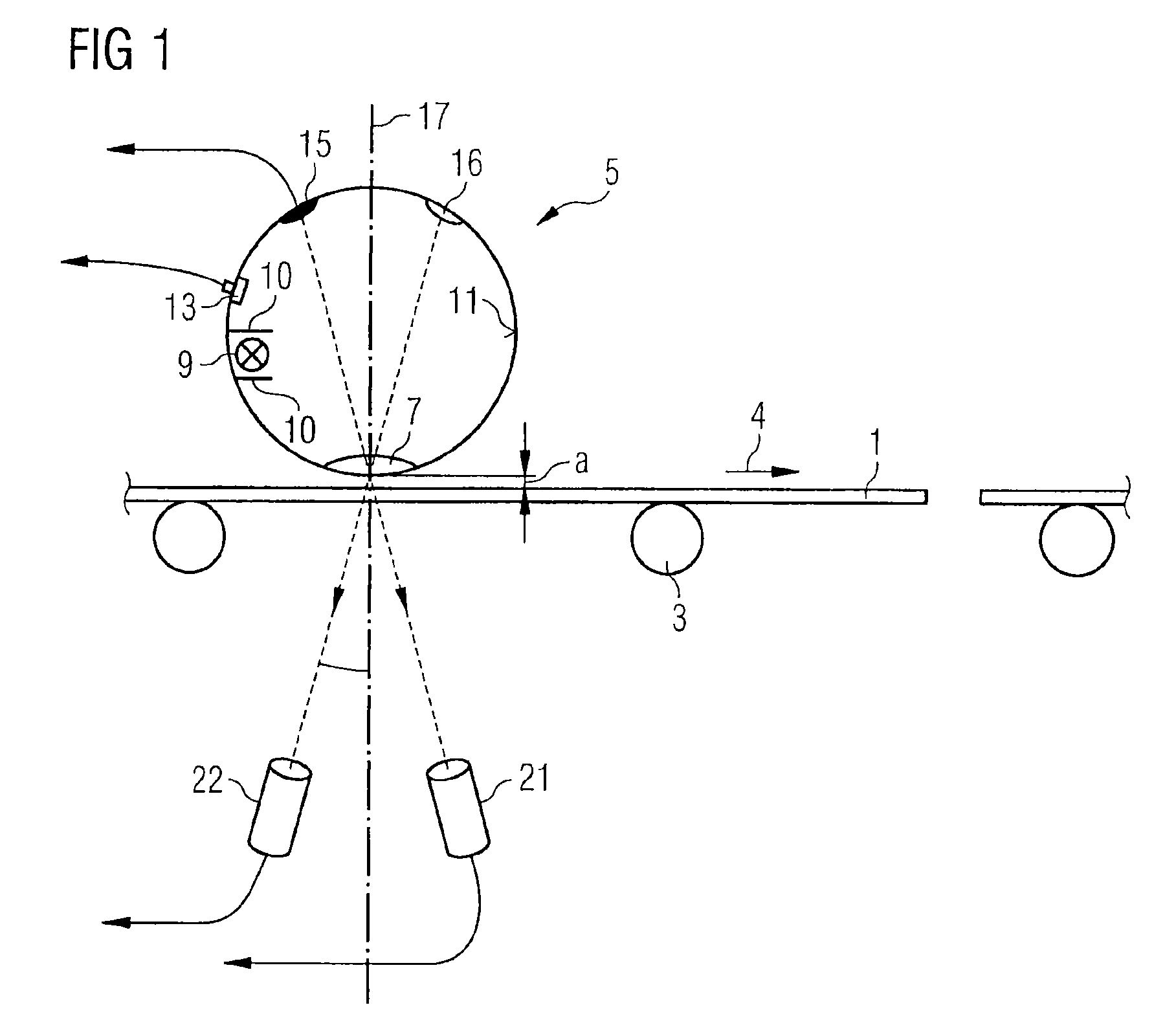
[0022]A finite distance a, and particularly if the latter fluctuates on account of the relative movement, leads to an influencing of the measurement signal of a scattering measurement object, since a finite proportion with a large angle no longer impinges on the measurement object from the illumination source on account of said distance. Moreover, when an Ulbricht sphere or a comparable illumination source is used, an increased light incidence in the sphere can be registered, which corrupts the characteristics of the illumination source. These effects are intensified with increasing scattering and increasing reflection of the measurement object and corrupt both measured transmission values.
[0030]Supplementarily, the non-linearity of the measurement channels can be eliminated by means of a fourth measurement on a further known, scattering sample having transmission and scattering properties deviating from the above-mentioned sample.

Problems solved by technology

On account of this measurement sequence, however, it is not possible to perform haze measurements in an inline coating apparatus for quality assurance, in which usually planar substrates are coated continuously and in relatively large quantities.

Method used


Image

  • Method and device for measuring optical characteristic variables of transparent, scattering measurement objects
  • Method and device for measuring optical characteristic variables of transparent, scattering measurement objects
  • Method and device for measuring optical characteristic variables of transparent, scattering measurement objects

Examples


Embodiment Construction

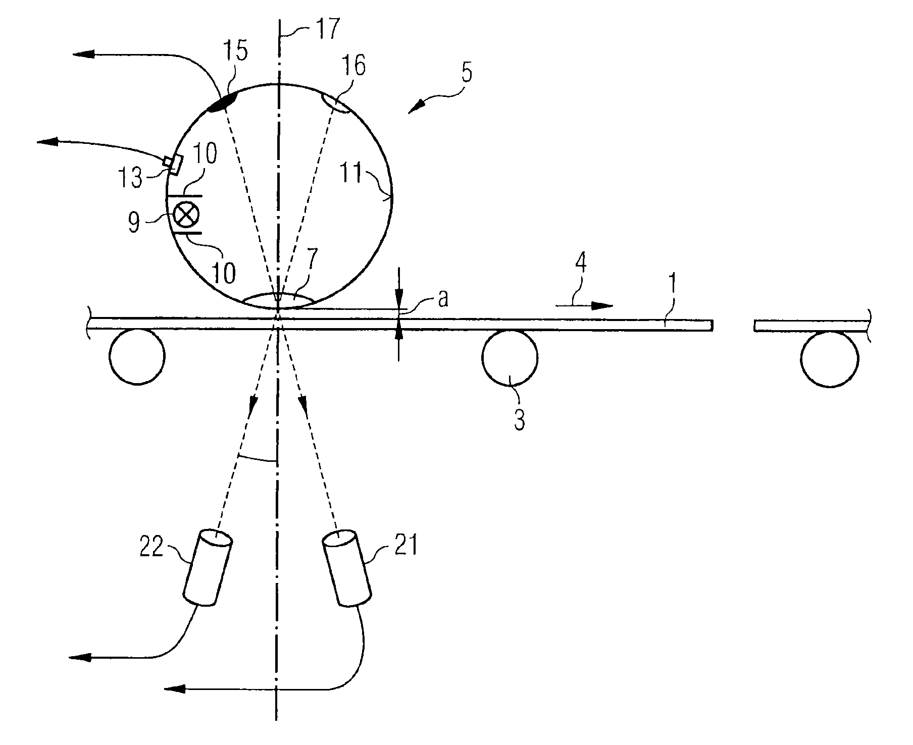
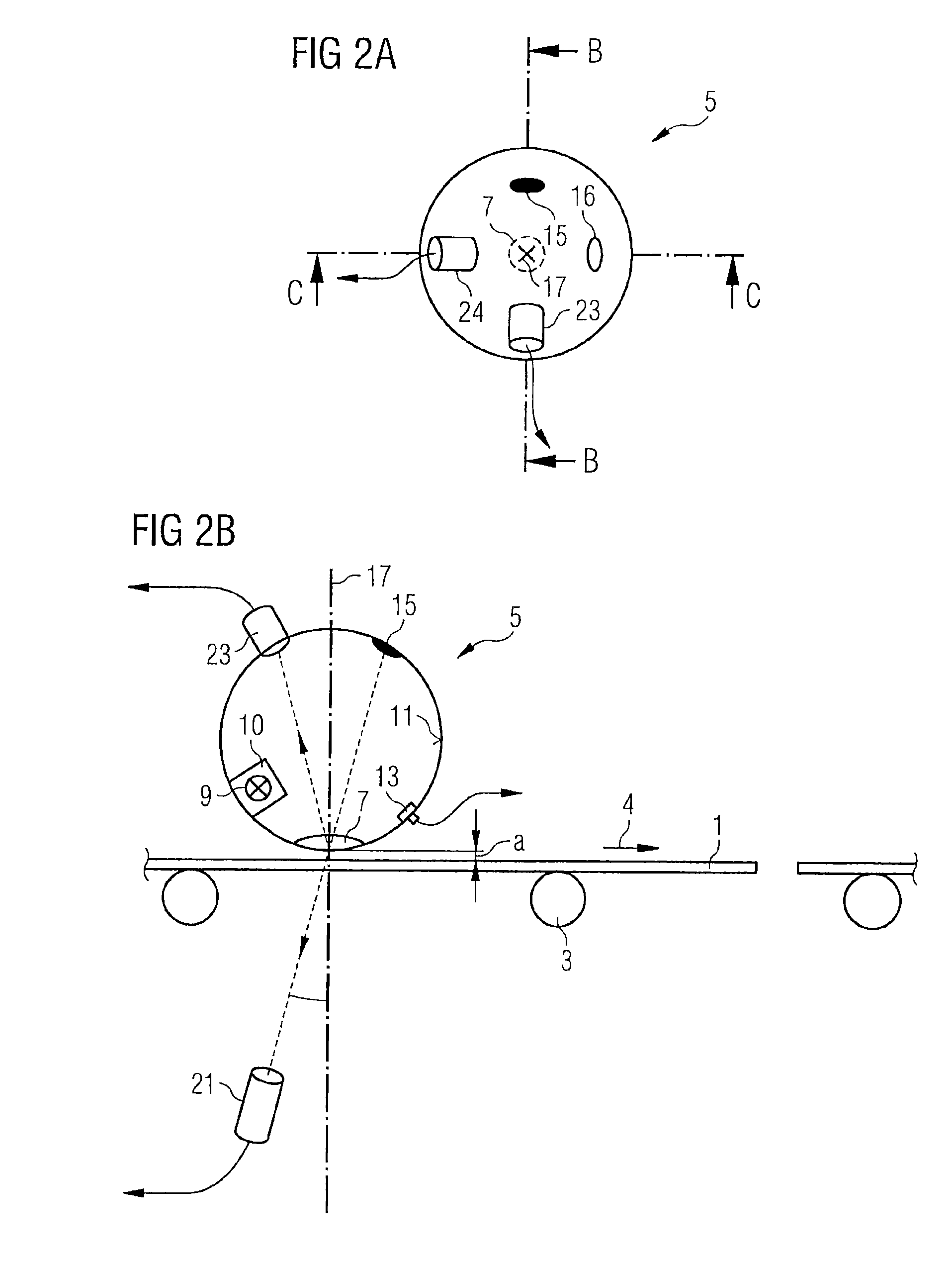
[0042]The measuring device in accordance with FIG. 1 comprises an illumination source 5, in the illustrated exemplary embodiment an Ulbricht sphere, which is arranged above a flat, plate-type and measurement object 1, designated generally and thus also hereinafter as substrate 1. The substrate 1 is transparent and has a transparent and scattering coating. A sequence of substrates 1 is illustrated, which is moved by means of a transport device 3 in a substrate transport direction 4 continuously or discontinuously through a coating apparatus (not illustrated). In the coating apparatus, a transparent electrically conductive layer is continuously applied on the sequence of substrates and subjected to after treatment e.g. by means of a suitable etching method for producing the light-scattering property. The haze of the coated substrate is intended to be measured constantly and in a distributed manner on the substrate by means of the measuring device illustrated. Alternatively, other tran...


PUM


Abstract

A method and device are provided for measurement of various transmission and reflection values of transparent measurement objects having transparent layers in an inline coating system, and particularly the turbidity of the measurement object during a relative movement between the measurement object and measuring device. Transmission fractions are measured in two different radiation directions of a lighting source emitting diffuse light by two photodetectors, by which a fraction of diffuse light of the lighting source is suppressed in one direction.

Description

CROSS REFERENCE TO RELATED APPLICATIONS[0001]This application is a national stage filing under section 371 of International Application No. PCT / EP2010 / 061695 filed on Aug. 11, 2010, and published in German on Mar. 17, 2011 as WO 2011 / 029685 A1 and claims priority of German application No. 10 2009 040 642.5 filed on Sep. 9, 2009, the entire disclosure of these applications being hereby incorporated herein by reference.Background Art[0002]The invention relates generally to a method for measuring optical characteristic variables of transparent, scattering measurement objects and to a device for carrying out the method. It relates in particular to the measurement of various transmission and reflection values of plate- or strip-type substrates that are provided with transparent layers in an inline coating apparatus. The invention likewise relates to a device for carrying out the method.[0003]Optical characteristic variables obtained by reflection and / or transmission measurements are ofte...

Claims


Application Information

Patent Timeline
Patent Type & Authority Patents(United States)
IPC IPC(8): G01J1/04
CPCG01N21/474G01N21/59G01N21/896G01N21/8422G01N2021/4754G01N2021/4783G01N2201/065G01N2021/8427
Inventor PROEHL, HOLGERKNOTH, THOMASSCHOESSLER, TINADIMER, MARTIN
Owner VON ARDENNE ANLAGENTECHNIK GMBH
Learn More