Power connector assembly with improved terminals

a technology of power connectors and assembly parts, applied in the direction of coupling contact members, coupling device connections, printed circuits, etc., can solve the problems of power terminal damage and affect the stability of connection, and achieve the effect of high-performance current transmission

Active Publication Date: 2012-09-11
STARCONN ELECTRONICS SU ZHOU CO LTD
View PDF63 Cites 13 Cited by
  • Summary
  • Abstract
  • Description
  • Claims
  • Application Information

AI Technical Summary

Benefits of technology

[0008]The present disclosure provides a power connector assembly with improved terminals, which at least provides well-connected power terminals and high performance current transmission.
[0010]Therefore, the present disclosure has advantages as followed. The bulge portion can increase the contacting stress between the first power-terminal sets and the second power-terminal sets, such that the contact resistance can be reduced and a stable contact can be provided, thereby providing excellent electrical contact.
[0011]Further, the present disclosure can enhance the mounting stability of power terminals. The first power-terminal set has a pair of separate first power terminals. Each of the first and second power terminals includes a fixing portion and a plurality of soldering legs downward extended from the fixing portion, wherein the contacting portion is forward extended from the fixing portion. Each fixing portion has four corners respectively wedged in the first and second terminal receiving groove. Therefore, the fixing portions of the power terminals are well fixed in the terminal receiving grooves, which would prevent the power terminals from drawing back and avoid to be loosened.

Problems solved by technology

With such configuration, a twisting torque resulted from the impact during the connection may happen to the terminals, and the terminals may be loosened, then the connection stability may be affected.
Even, the power terminals may be damaged.

Method used


Image

  • Power connector assembly with improved terminals
  • Power connector assembly with improved terminals
  • Power connector assembly with improved terminals

Examples


Embodiment Construction

[0019]In order to better understand the objective, structure, characteristics, and effects of the present disclosure, a description relating thereto will be made with reference to preferred embodiments thereof and the accompanying drawings.

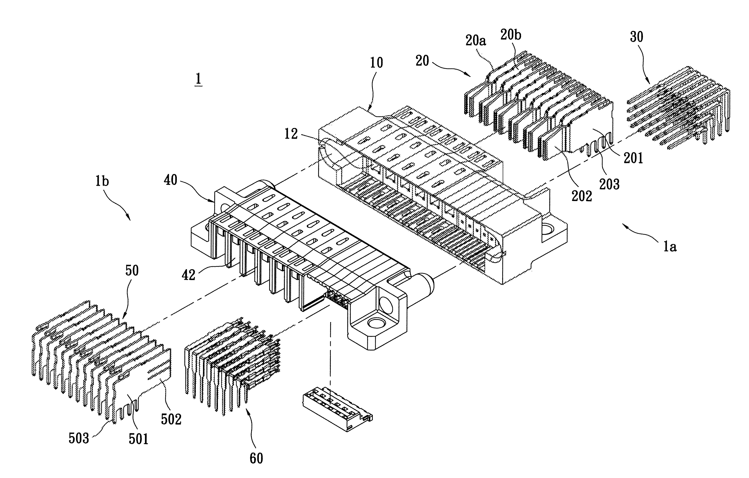
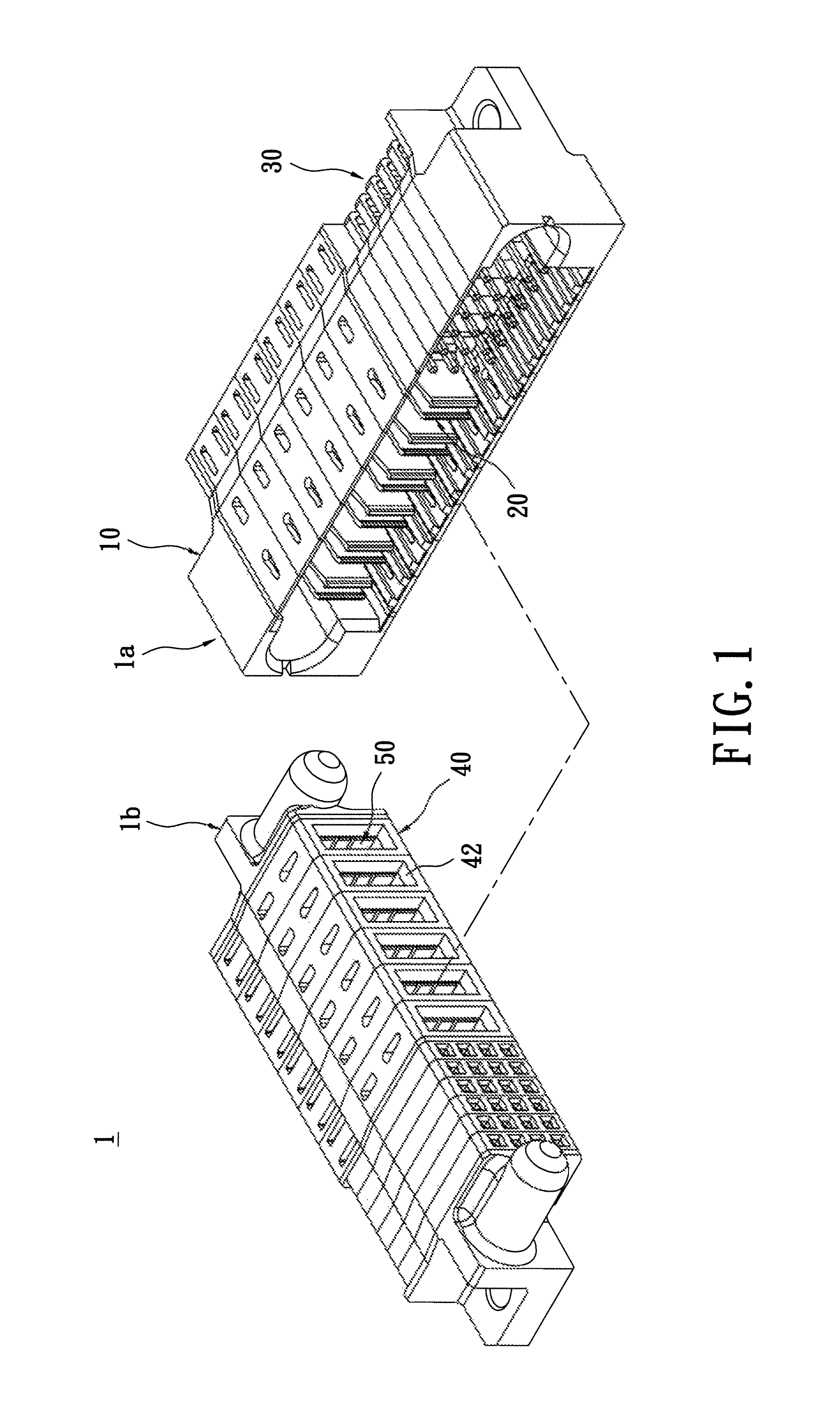
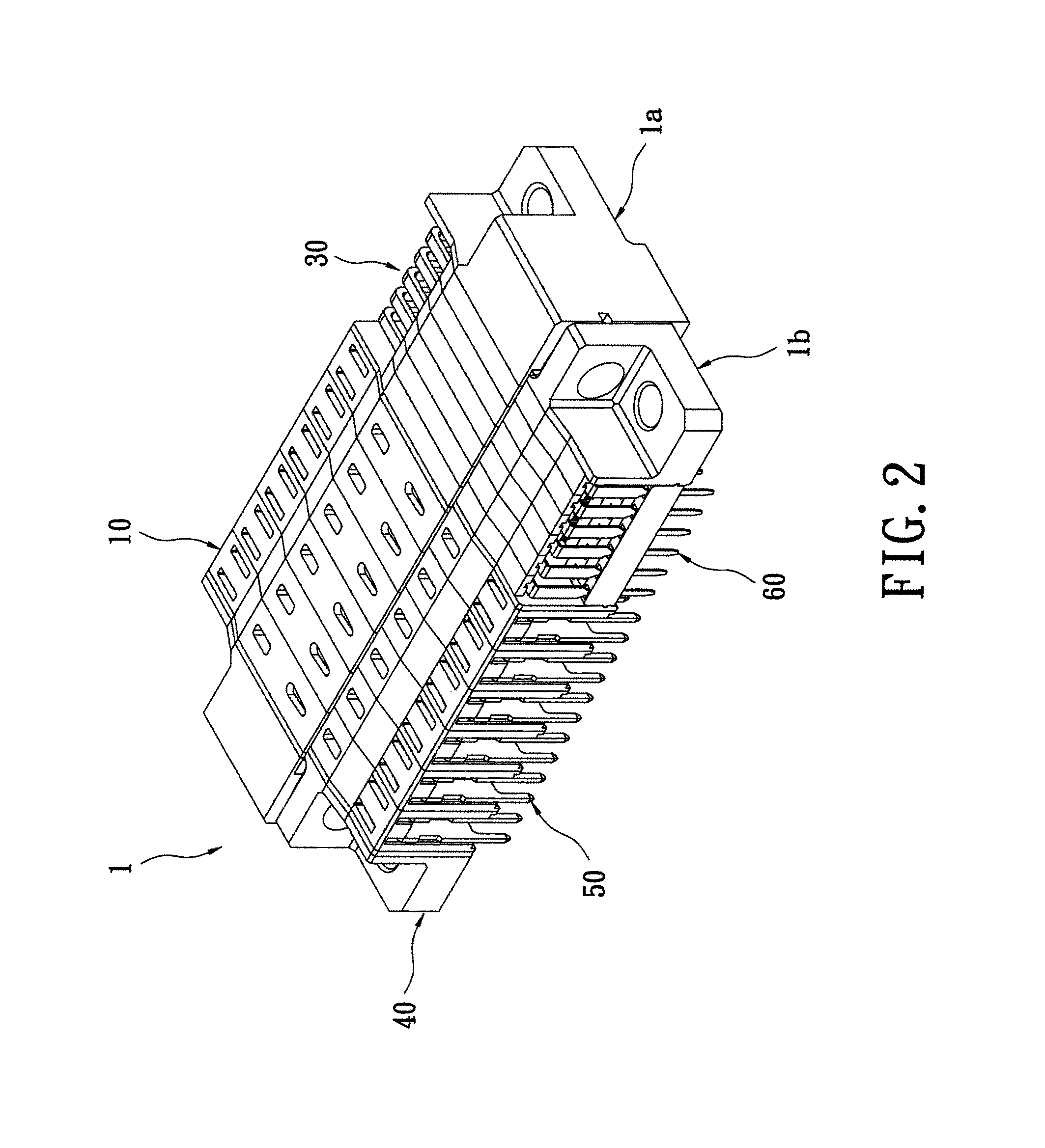
[0020]Reference is made to FIGS. 1 to 2, which are separate perspective view and assembled perspective view of a power connector assembly with improved terminals according to the present disclosure. The present disclosure provides a power connector assembly with improved terminals 1, which includes a first electrical connector 1a and a second electrical connector 1b. The first electrical connector 1a belongs to plug-type electrical connector, and the second electrical connector 1b belongs to socket-type electrical connector. Both are soldered fixedly on a circuit board (not shown). As shown in FIG. 2, the first electrical connector 1a is plugged in the second electrical connector 1b for transmitting power and signals.

[0021]Please refer to FIG. 3, ...


PUM


Abstract

A power connector assembly with improved terminals includes a first electrical connector and a second electrical connector. The first electrical connector has a first insulated body and a plurality of first power-terminal sets received in the first insulated body. The second electrical connector has a second insulated body and a plurality of second power-terminal sets received in the second insulated body. Each of the first power-terminal sets is contacted with each of the second power-terminal sets correspondingly. Each second power-terminal set has a pair of separate second power terminals. Each second power terminal has a contacting portion for contacting with the first power-terminal set. Each contacting portion is protruded with at least one bulge portion toward the first power-terminal set from a side thereof.

Description

BACKGROUND OF THE INVENTION[0001]1. Field of the Invention[0002]The present disclosure is related to a power connector assembly with improved terminals, especially to a connector assembly including a plug connector and a socket connector for power transmission between the circuit boards.[0003]2. Description of Related Art[0004]To design a plug connector and a socket connector for transmitting power between the circuit boards should consider not only the electrical signal, but also the electrical power. Although the part of electrical signal is equipped with low current, the part of electrical power with comparative higher current may influence the electrical characteristic potentially.[0005]The part of electrical power includes a plurality of male power terminals and female power terminals connected to each other. The connection of each set of power terminals must not only be good and secure, but further striving for high performance current transmission, thus machines, such as a co...

Claims


Application Information

Patent Timeline
Patent Type & Authority Patents(United States)
IPC IPC(8): H01R12/00
CPCH01R13/11H01R27/02H01R12/714
Inventor KE, YU-FENGHUANG, SHENG-HSIANGCHIN, HSIEN-NING
Owner STARCONN ELECTRONICS SU ZHOU CO LTD
Why Eureka
Try Eureka