Irrigated catheter having a porous tip electrode

a technology of irrigated catheters and tip electrodes, which is applied in the field of irrigated catheters having porous tip electrodes, can solve the problems of sintered metal particles disintegrating and breaking away from the electrode structure, formation of electrically non-conductive lesion within cardiac tissue, and stagnant area between electrodes and tissue, etc., to achieve the effect of promoting fluid flow, minimizing fluid pressure drop through the material, and improving resistance to disintegration during irrigation

Active Publication Date: 2012-09-11
BIOSENSE WEBSTER INC
View PDF20 Cites 46 Cited by
  • Summary
  • Abstract
  • Description
  • Claims
  • Application Information

AI Technical Summary

Benefits of technology

[0012]The porous tip electrode comprises sintered non-conductive material. The sintered material may be made from any suitable non-conductive polymer or ceramic material. The sintered particles comprise both small particles and large particles, the large particles having a mean diameter at least about 2.5 times greater, and preferably, about 4 times greater, than the mean diameter of the small particles. The use of differently sized particles helps control the porosity of the sintered material, promotes uniform flow of fluid through the porous material, and minimizes fluid pressure drop through the material. The porous tip electrode is covered with a thin metal coating that is webbed, or otherwise porous, with openings through which fluid can pass to the outer surface of the tip electrode. The sintered polymeric or ceramic material has improved resistance to disintegration during irrigation. The metal coating improves overall structural stability of the tip electrode and serves as an electrode for conducting radio-frequency energy to the target tissue.

Problems solved by technology

The tissue is heated sufficiently to cause cellular destruction in the cardiac tissue resulting in formation of a lesion within the cardiac tissue which is electrically non-conductive.
However, there is typically a stagnant area between the electrode and tissue which is susceptible to the formation of dehydrated proteins and coagulum.
However, during irrigation the sintered metal particles can disintegrate and break away from the electrode structure.

Method used


Image

  • Irrigated catheter having a porous tip electrode
  • Irrigated catheter having a porous tip electrode
  • Irrigated catheter having a porous tip electrode

Examples


Embodiment Construction

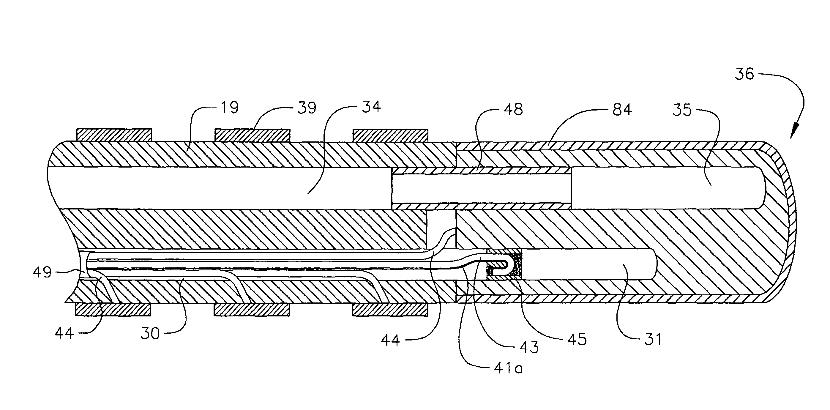
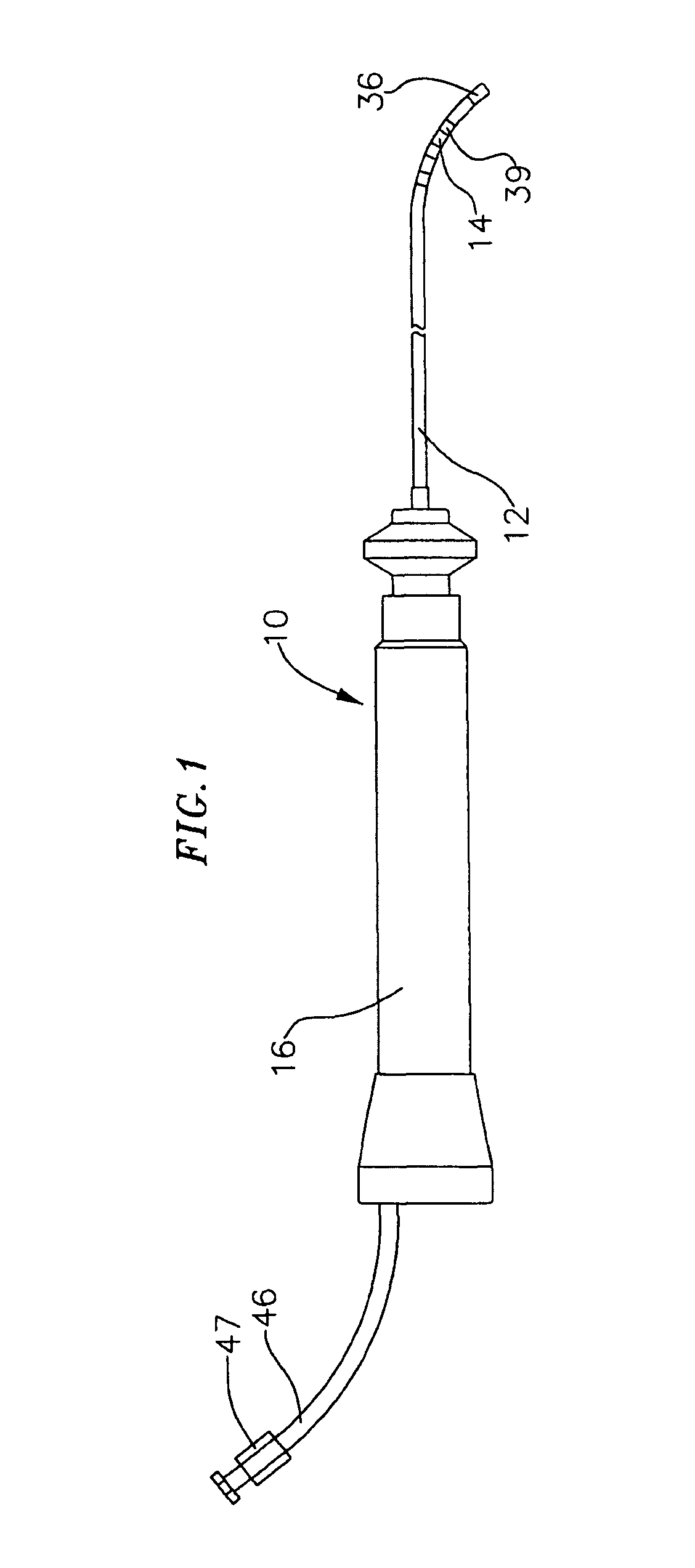
[0026]In a particularly preferred embodiment of the invention, there is provided a steerable catheter having an irrigated tip. As shown in FIGS. 1 to 4, catheter 10 comprises an elongated catheter body 12 having proximal and distal ends, a tip section 14 at the distal end of the catheter body 12, and a control handle 16 at the proximal end of the catheter body 12.

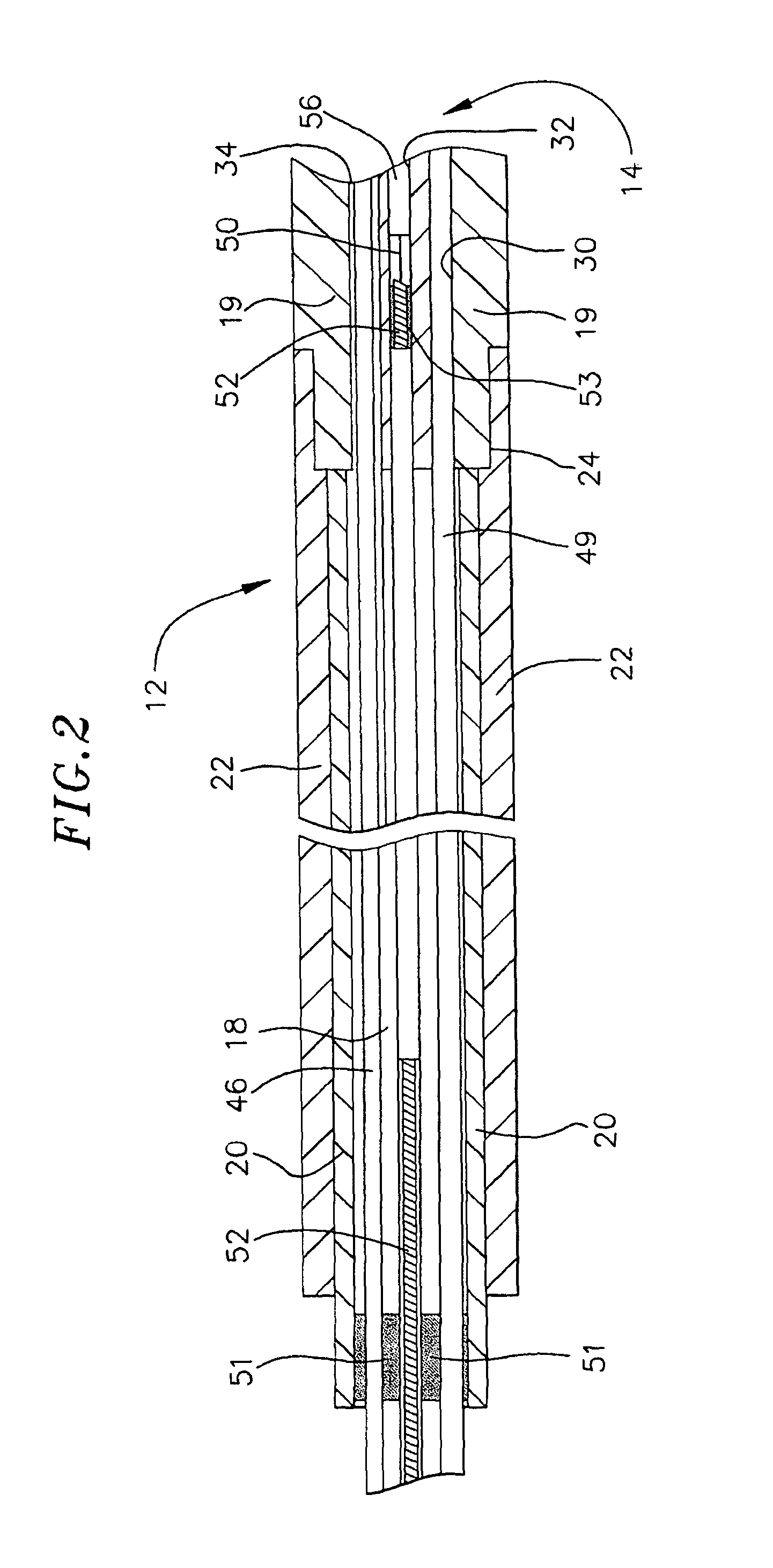
[0027]With reference to FIG. 2, the catheter body 12 comprises an elongated tubular construction having a single, axial or central lumen 18. The catheter body 12 is flexible, i.e., bendable but substantially non-compressible along its length. The catheter body 12 can be of any suitable construction and made of any suitable material. A presently preferred construction comprises an outer wall 22 made of a polyurethane or PEBAX. The outer wall 22 comprises an imbedded braided mesh of high-strength steel, stainless steel or the like to increase torsional stiffness of the catheter body 12 so that, when the control handle 16 is r...


PUM

PropertyMeasurementUnit
thicknessaaaaaaaaaa
temperatureaaaaaaaaaa
diameteraaaaaaaaaa

Abstract

A porous tip electrode catheter is provided. The porous tip electrode comprises a porous material through which fluid can pass. The porous tip electrode is covered with a thin coating of conductive metal having openings through which fluids can pass.

Description

FIELD OF THE INVENTION[0001]The present invention is directed to an irrigated catheter having a porous tip electrode.BACKGROUND OF THE INVENTION[0002]Electrode catheters have been in common use in medical practice for many years. They are used to map electrical activity in the heart and to ablate sites of aberrant electrical activity.[0003]In use, the electrode catheter is inserted into a major vein or artery, e.g., the femoral artery, and then guided into the chamber of the heart which is of concern. Within the heart, the ability to control the exact position and orientation of the catheter tip is critical and largely determines the usefulness of the catheter.[0004]In certain applications, it is desirable to have the ability to inject and / or withdraw fluid through the catheter. One such application is a cardiac ablation procedure for creating lesions which interrupt errant electrical pathways in the heart. Traditionally, this has been accomplished with an irrigated tip catheter.[00...

Claims


Application Information

Patent Timeline
Patent Type & Authority Patents(United States)
IPC IPC(8): A61B18/14A61B18/00
CPCA61B18/1492A61B2018/00029A61B2018/00065A61B2018/00077A61B2018/00148A61B2019/5251A61B2034/2051
Inventor PLAZA, CLAUDIO P.
Owner BIOSENSE WEBSTER INC
Why Eureka
Try Eureka