
Suspension system

a suspension system and suspension technology, applied in the direction of cycle equipment, instruments, transportation and packaging, etc., can solve the problems of difficult to satisfactorily suppress the vibration, the suspension initiates the work with delay relative to the actual vibration, etc., and achieves the effect of reducing the distance between the sprung and unsprung portions

Inactive Publication Date: 2012-09-11
TOYOTA JIDOSHA KK
View PDF34 Cites 22 Cited by
  • Summary
  • Abstract
  • Description
  • Claims
  • Application Information

AI Technical Summary

Benefits of technology

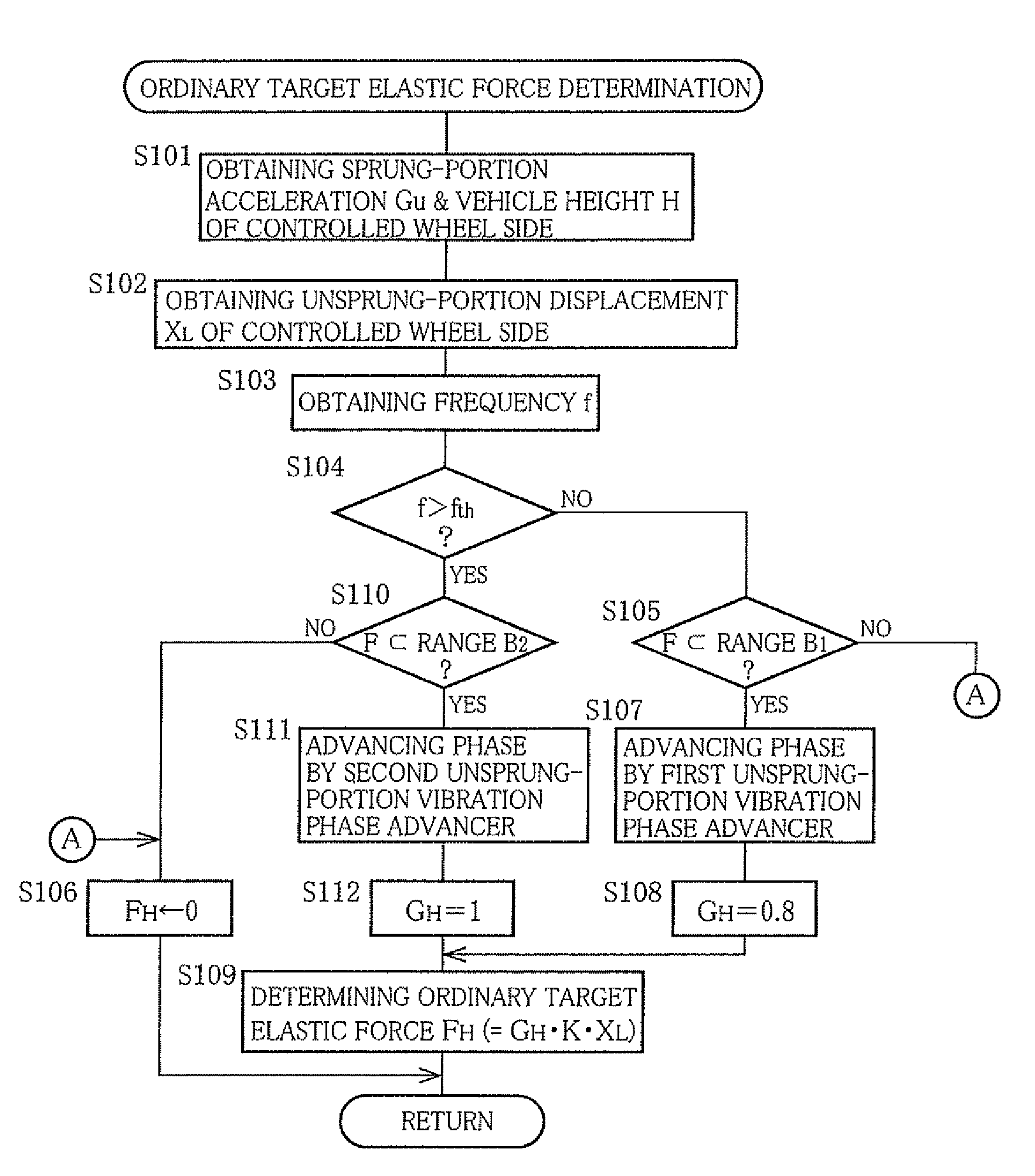
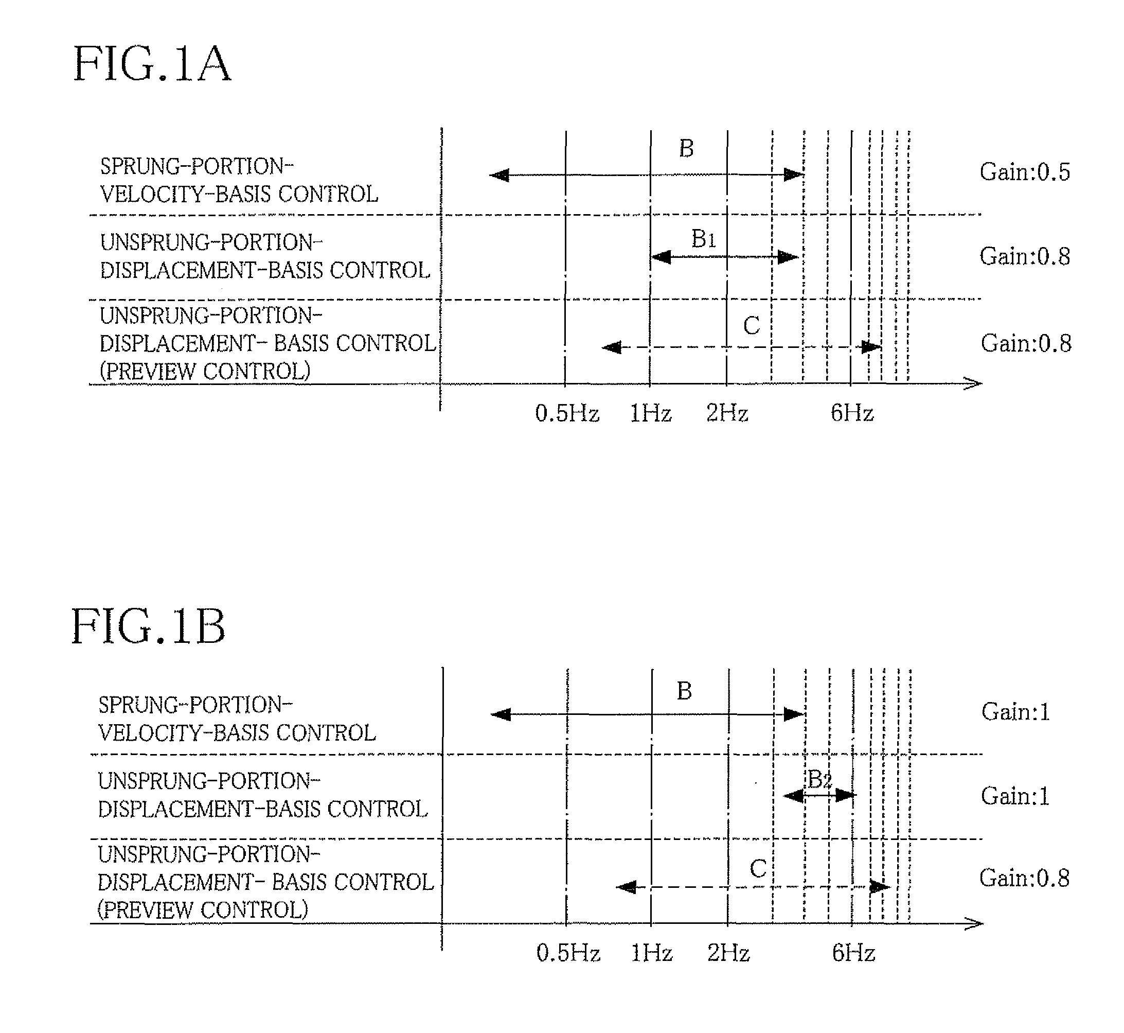
[0005]In the present suspension system, the vertical vibration of each of the at least one of the sprung and unsprung portions of the vehicle is obtained, the obtained vibration is subjected to the phase advance processing performed by the processing device, and the suspension is controlled based on the processed vibration. In general, the suspension initiates working with delay relative to actual vibration due to factors such as response delay of an actuator included in the suspension. Particularly, when the response delay time of the actuator is long, there is a case where it is difficult to satisfactorily suppress the vibration. In such a case, it might be possible to reduce influence of the response delay, by controlling the actuator based on the processed vibration that has been subjected to the phase advance processing. However, for example, where the phase of the vibration is advanced by a degree suitable for suppressing vibration having a frequency equal to or close to a sprung-portion resonance frequency, the vibration could be satisfactorily suppressed if the vibration has the frequency equal to or close to the sprung-portion resonance frequency, but could not be satisfactorily suppressed if the vibration has the frequency equal to or close to an unsprung-portion resonance frequency. On the contrary, where the phase of the vibration is advanced by a degree suitable for suppressing vibration having the frequency equal to or close to the unsprung-portion resonance frequency, the vibration could not be satisfactorily suppressed if the vibration has the frequency equal to or close to the unsprung-portion resonance frequency. In view of such a problem, the processing device included in the present suspension system is arranged to have the plurality of characteristics different from each other with respect to the degree by which the phase of the obtained vertical vibration is advanced, so that one of the plurality of characteristics is selected based on the frequency of the obtained vertical vibration. Consequently, irrespective of whether the frequency of the vibration is close to the sprung-portion resonance frequency or unsprung-portion resonance frequency, the vibration can be satisfactorily suppressed whereby a ride comfort can be improved.
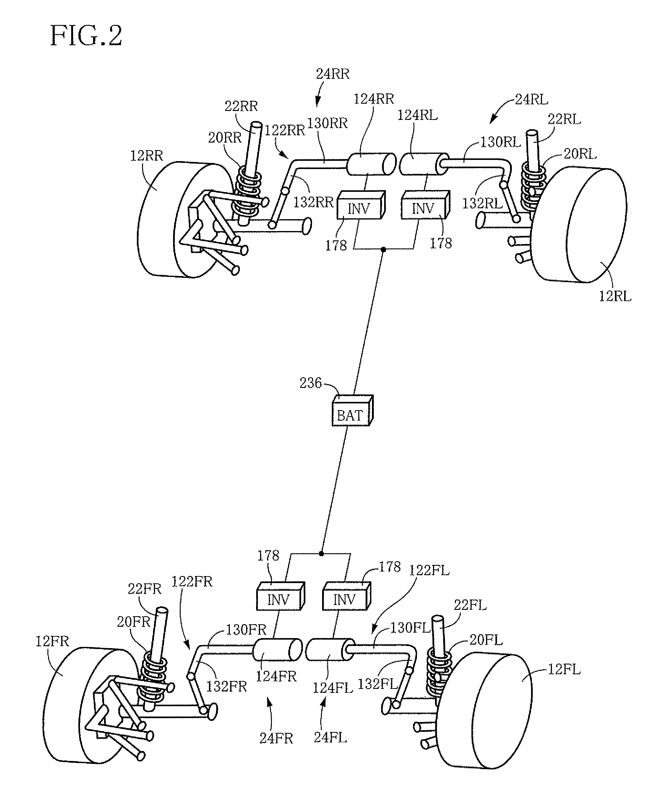
[0045]When the electric motor is rotated in a direction opposite to the above-described certain direction from the reference state, the distance between the sprung and unsprung portions is reduced. In this instance, the elastic force of the first elastic member and the elastic force of the second elastic member act in respective directions that are opposite to each other. When the elastic force of the second elastic member is increased as a result of reduction in the distance between the sprung and unsprung portions, the elastic force of the first elastic member (acting in the direction opposite to the direction of the elastic force of the second elastic member) is increased.

Problems solved by technology

In general, the suspension initiates working with delay relative to actual vibration due to factors such as response delay of an actuator included in the suspension.
Particularly, when the response delay time of the actuator is long, there is a case where it is difficult to satisfactorily suppress the vibration.

Method used


Image

  • Suspension system
  • Suspension system
  • Suspension system

Examples


Embodiment Construction

[0011]There will be described various modes of the invention deemed to contain claimable features for which protection is sought. Each of these modes of the invention is numbered like the appended claims and depends from the other mode or modes, where appropriate, for easier understanding of the technical features disclosed in the present specification. It is to be understood that the present invention is not limited to the technical features or any combinations thereof which will be described, and shall be constructed in the light of the following descriptions of the various modes and preferred embodiments of the invention. It is to be further understood that a plurality of elements or features included in any one of the following modes of the invention are not necessarily provided all together, and that the invention may be embodied with selected at least one of the elements or features described with respect to the same mode. It is to be still further understood that a plurality ...


PUM


Abstract

A suspension system including: (a) a vibration obtaining device configured to obtain vertical vibration of each of at least one of a sprung portion and an unsprung portion of a vehicle; (b) a processing device configured to subject the obtained vibration to a phase advance processing, and having a plurality of characteristics different from each other with respect to a degree by which a phase of the obtained vibration is advanced; (c) a characteristic selector configured to select one of the plurality of characteristics, based on frequency of the obtained vibration of each of at least one of the sprung and unsprung portions, whereby the obtained vibration is subjected to the phase advance processing that is performed in accordance with the selected one of the plurality of characteristics of the processing device; and (d) a suspension controller configured to control a suspension disposed between the sprung and unsprung portions, based on the vibration subjected to the phase advance processing.

Description

TECHNICAL FIELD[0001]The present invention relates in general to control of a vehicle suspension, and more particularly to processing of vibration that is obtained by a vibration obtaining device.BACKGROUND ART[0002]JP-H08-258529A discloses an arrangement with a plurality of phase compensation filter means, one of which is selected depending on a resonance frequency of a sprung portion. Specifically, when the resonance frequency is high, one of the filter means which has a characteristic of small phase delay is selected. When the resonance frequency is low, one of the filter means which has a characteristic of large phase delay is selected. In this arrangement, when a load applied to the sprung portion is small and accordingly the resonance frequency is high, it is possible to improve responsiveness and satisfactorily obtain a vibration suppressing effect, by selecting the filter means having the characteristic of small phase delay. JP-H05-319056A discloses an arrangement with phase...

Claims


Application Information

Patent Timeline
Patent Type & Authority Patents(United States)
IPC IPC(8): B60G17/00B60G17/015B60G17/018B60G21/055F16F15/02
CPCB60G17/0157B60G17/018B60G17/025B60G21/0555B60G17/0165B60G2200/184B60G2202/134B60G2202/42B60G2400/102B60G2400/206B60G2400/208B60G2400/252B60G2400/821B60G2400/91B60G2400/954B60G2500/30B60G2600/182B60G2600/60B60G2800/162
Inventor KAJINO, HIDEONORIKANDA, RYO
Owner TOYOTA JIDOSHA KK
Learn More