Water heater

a water heater and mounting plate technology, applied in the field of indoor mounting water heaters, can solve the problems of increased cost, difficult to supply hot water at a low set temperature, and leakage of combustion exhaust gas from an intermediate portion of the exhaust duct, so as to improve heat efficiency

Active Publication Date: 2012-09-18
RINNAI CORP
View PDF10 Cites 21 Cited by
  • Summary
  • Abstract
  • Description
  • Claims
  • Application Information

AI Technical Summary

Benefits of technology

[0008]The present invention has been made in view of the above circumstances, and accordingly an object thereof is to provide a water heater in which the draft force at the time when the combustion capacity is decreased by the capacity changeover mechanism can be prevented from decreasing, and also the heat efficiency can be improved.
[0010]According to the present invention, since the air sent from the air supply fan is supplied to only a part of the air supply chamber corresponding to a burning burner group by the air supply changeover mechanism, the air sent from the air supply fan is not supplied to a part of the air supply chamber corresponding to a non-burning burner group. Therefore, unlike the conventional example, a phenomenon does not occur that air is supplied to a non-burning burner group, the air is mixed with combustion exhaust gas in the upper part of the combustion housing, and thereby the temperature of combustion exhaust gas is decreased. Therefore, even if the combustion capacity is decreased by the capacity changeover mechanism, combustion exhaust gas having a high temperature can be discharged to the exhaust duct, so that the draft force can be kept high. As a result, the pressure in the exhaust duct becomes negative, so that combustion exhaust gas can be prevented from leaking from an intermediate portion of the exhaust duct even if the exhaust opening of the water heater is connected to a low gastight exhaust duct.
[0011]Also, unlike the conventional example, heat is not absorbed by the contact of the heat exchanger in the combustion housing with the air passing through a non-burning burner group, so that the heat efficiency can be improved. Even if the combustion capacity is decreased by the capacity changeover mechanism, the temperature of combustion exhaust gas can be kept high, so that the occurrence of drain caused by the condensation of water vapor in the combustion exhaust gas can be prevented.

Problems solved by technology

In the case where the above-described water heater is used indoors by connecting the exhaust opening of the water heater to an exhaust duct already provided in a house or the like, if the gastightness of the exhaust duct is low, combustion exhaust gas may leak from an intermediate portion of the exhaust duct.
However, the replacement of exhaust duct requires large-scale construction work, which results in an increase in cost.
However, there arises a problem in that hot water is difficult to be supplied at a low set temperature.
Also, in the conventional water heater, if the combustion capacity is decreased by the capacity changeover mechanism, some of the air supplied from the air supply fan passes through a non-burning burner group and absorbs heat from the heat exchanger, which presents a problem of decreased heat efficiency.

Method used


Image

  • Water heater
  • Water heater
  • Water heater

Examples


first embodiment

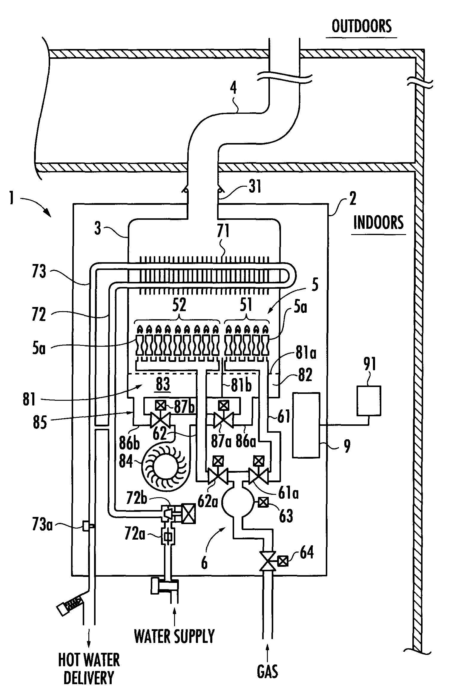
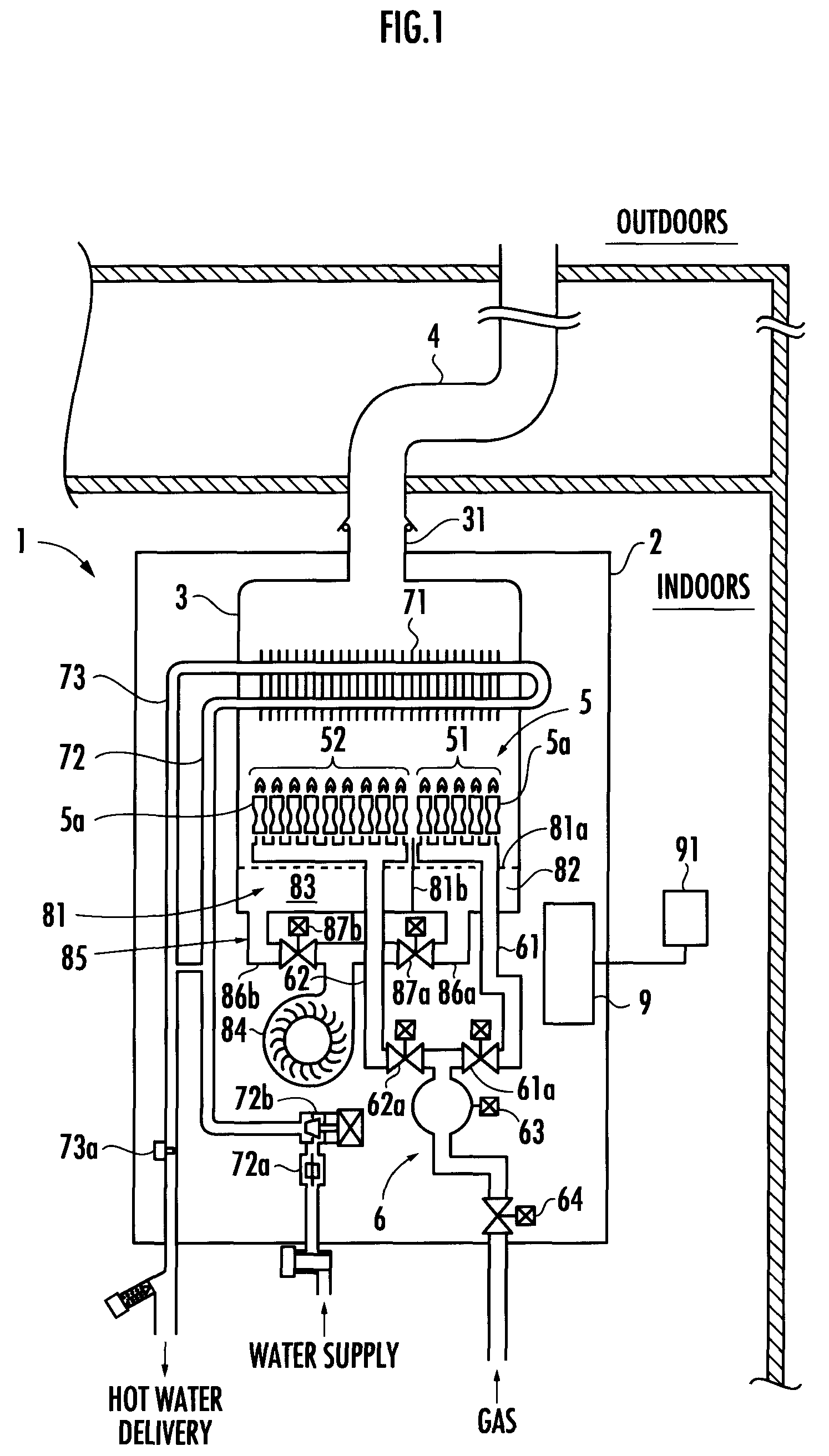
[0016]A water heater 1 of a first embodiment in accordance with the present invention shown in FIG. 1 is mounted indoors, and comprises a combustion housing 3 stored in a housing 2. At the upper end of the combustion housing 3, an exhaust opening 31 connected to an exhaust duct 4 extending to the outdoors is provided so as to be exposed above the housing 2. The exhaust duct 4 is formed by connecting a plurality of cylinder bodies, so that the gastightness depends on the sealing ability of the connecting part.

[0017]In the lower part of the combustion housing 3, a burner unit 5 is stored. The burner unit 5 is made up of a first burner group 51 formed by a relatively small number of unit burners 5a and a second burner group 52 formed by a relatively large number of unit burners 5a.

[0018]The burner unit 5 is connected with a gas supply path 6 for supplying fuel gas. The downstream side of the gas supply path 6 branches into a first branch path 61 connected to the first burner group 51 ...

second embodiment

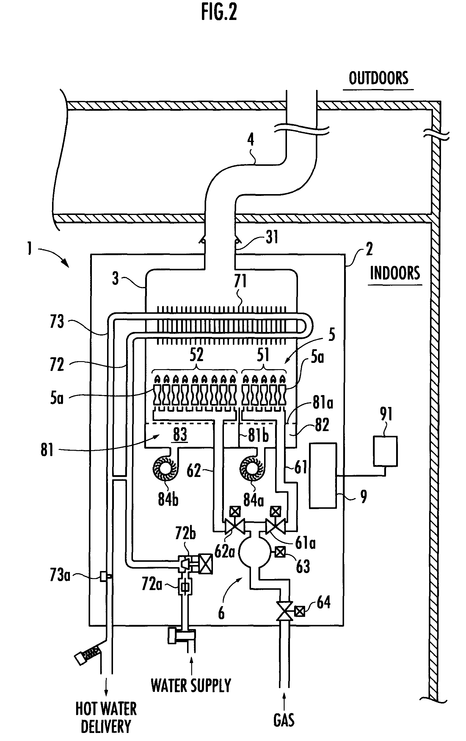
[0030]The controller 9 of the water heater 1 of the second embodiment drives the first air supply fan 84a and the second air supply fan 84b when the first burner group 51 and the second burner group 52 are burned, drives the second air supply fan 84b and prohibits the first air supply fan 84a from driving or weakly drives the first air supply fan 84a when the second burner group 52 only is burned, and drives the first air supply fan 84a and prohibits the second air supply fan 84b from driving or weakly drives the second air supply fan 84b when the first burner group 51 only is burned.

[0031]The term “weak drive” means a weak drive for preventing the combustion exhaust gas of a burning burner group from being discharged to the outdoors via a part (the first air supply chamber 82 or the second air supply chamber 83) of the air supply chamber 81 corresponding to a non-burning burner group and an air supply fan (the first air supply fan 84a or the second air supply fan 84b) communicating...


PUM


Abstract

There is provided an indoor mounting water heater in which combustion exhaust gas is discharged to the outdoors via an exhaust duct, wherein a decrease in draft force caused when the number of burner groups to be burned is reduced by a capacity changeover mechanism to decrease the combustion capacity can be prevented, and the heat efficiency can be improved. An air supply chamber 81 is divided into a plurality of parts 82 and 83 corresponding to a plurality of burner groups 51 and 52. The air sent from an air supply fan 84 is supplied to only a part of the air supply chamber corresponding to a burning burner group.

Description

BACKGROUND OF THE INVENTION[0001]1. Field of the Invention[0002]The present invention relates to an indoor mounting water heater in which combustion exhaust gas is discharged to the outdoors via an exhaust duct.[0003]2. Description of the Related Art[0004]Conventionally, there has been known a water heater comprising a combustion housing having an exhaust opening at the upper end thereof, a burner unit which is stored in the lower part of the combustion housing and configured by a plurality of burner groups, a heat exchanger for hot water supply which is stored in the upper part of the combustion housing, an air supply fan for supplying combustion air to the burner unit via an air supply chamber provided on the lower side of the arrangement section of burner unit in the combustion housing, and a capacity changeover mechanism for changing over the combustion capacity by changing the number of burner groups to be burned (for example, refer to Japanese Patent Laid-Open No. 11-294761).[...

Claims


Application Information

Patent Timeline
Patent Type & Authority Patents(United States)
IPC IPC(8): F22B5/00
CPCF23N3/065F23N3/08F24D12/02F24H1/46F24H1/523F24H9/2042F24D2200/043Y02B30/14Y02B30/00F24H15/365F24H15/156F24H15/238F24H15/45F24H15/174F24H15/345F24H15/219F24H15/32F24H15/31
Inventor ANDO, MASAKAZU
Owner RINNAI CORP
Why Eureka
Try Eureka