Jam-tollerant actuator

a technology of electromechanical actuators and jamming, which is applied in the direction of wing adjustment, stopper details, aircraft transmission means, etc., can solve the problems of preventing the actuator from operating efficiently and/or safely, proposals suffer from various disadvantages, and failure-once systems

Active Publication Date: 2012-09-18
AIRBUS OPERATIONS LTD
View PDF44 Cites 27 Cited by
  • Summary
  • Abstract
  • Description
  • Claims
  • Application Information

AI Technical Summary

Benefits of technology

[0022]The actuator is therefore jam-tolerant in that in the event that the first gearbox fails, for example if it jams, the output of the actuator is not jammed, because the housing of the first gearbox may be allowed to rotate. The actuator may also be relatively lightweight and compact, because neither a large brake nor a large motor are required for the operation of the actuator, as a result of the provision of both the first gearbox and the second gearbox. The first and second gearboxes may be configured such that the probability of both gearboxes jamming simultaneously is negligible. The prime mover may also be designed such that there is negligible risk of the prime mover failing in such a way as to cause a jam in the prime mover. The actuator may therefore be configured to be jam-tolerant with a negligible risk of causing a permanent jam during operation at its output.
[0028]The actuator is preferably back-driveable, and more preferably back-driveable in the event of the first gearbox jamming. For example, both the second gearbox and the prime mover are preferably back-driveable. The second gearbox and the prime mover may be arranged in use to be back-driven in the event of jamming of the first gearbox. For example, the output of the first gearbox may be rotated by other means, requiring free movement of the second gearbox and prime mover, so as not to place any potentially damaging loads on the actuator whilst its output is rotated by such other means. The first gearbox need not of course be able to be back-driveable in the event of a jam of the first gearbox. Also, the first gearbox may be arranged not to be back-driveable, in particular when the first gearbox is not jammed.
[0032]Alternatively, or additionally, the actuator may be able to operate in an active manner in the event of the first gearbox becoming jammed, for example continuing to drive the output of the actuator. The drive may be provided by means of the prime mover first mentioned above (hereinafter the “first prime mover”). Alternatively, a second prime mover may be provided. Providing such a second prime mover may have the benefit of providing better redundancy in the actuator and may also reduce the need for complicated mechanisms for decoupling the first prime mover from the first gearbox when jammed. The actuator may include a second prime mover for producing rotary motion. The second prime mover may be associated with the second gearbox. For example, the second gearbox may be arranged in use to convert the rotary motion from the second prime mover into rotary motion having higher torque and lower speed.
[0035]The actuator may include a jamming mechanism, which is able in use to jam the first gearbox. In the event of a partial jam of the first gearbox, in which the first gearbox still functions but at significantly reduced efficiency, the jamming mechanism may be used to fully jam the first gearbox so that the actuator may function as if the first gear-box had fully jammed. The actuator may of course be arranged to function best in either of two distinct conditions, namely the first gearbox being free and the first gearbox being fully jammed. It may therefore be desirable to reduce the likelihood of the first gearbox being in any other condition, for example partially jammed. The jamming mechanism may be so arranged that when used it assists or causes the casing of the first gearbox to rotate at the same speed as the input motion. The jamming mechanism may for example be able to substantially prevent the gearbox casing from rotating relative to rest of gearbox. The jamming mechanism may for example comprise a clutch, brake or other means able to engage and disengage parts of the actuator in a manner (a) to facilitate free driving of the first gearbox (when not otherwise jammed) and (b) to substantially lock the gearbox so that rotation of the input shaft causes corresponding rotation of the casing and output of the first gearbox.
[0047]The whole of the first gearbox may thus be allowed to rotate, thereby preventing the jamming of the first gearbox from precluding movement of the component.
[0052]The method may be performed such that the component is able to move, after jamming of the first gearbox, without needing to irreversibly break or change any other parts used in the performance of the method.

Problems solved by technology

Electro-mechanical actuators, whether linear or rotary, include moving parts such as gears in gearboxes that may cause mechanical jamming of the actuator that prevents the actuator from operating efficiently and / or safely.
However, such proposals suffer from various disadvantages.
Such systems are fail-once systems and always require the replacement of at least part of the actuator, if the actuator is to again operate in its principal mode of operation.
The choice of a single threshold level may mean that the shear lugs fail when there is no jam and / or that the shear lugs do not fail soon enough in the event of a partial or full jam.
Certain proposals are simply too bulky or heavy for use in certain applications (see for example U.S. Pat. No. 4,215,592).
Such requirements may in certain applications be disadvantageous as a result of the reliance of a power source being available and / or the requirement for plural prime movers and therefore extra weight.
Certain proposals are limited by means of the gear ratios of the gearing within, and therefore the torques provided by, the actuator.
The actuator of U.S. Pat. No. 5,120,285 appears also to be susceptible to events that cause both the primary and secondary modes of operation to be inoperable.

Method used


Image

  • Jam-tollerant actuator
  • Jam-tollerant actuator
  • Jam-tollerant actuator

Examples


first embodiment

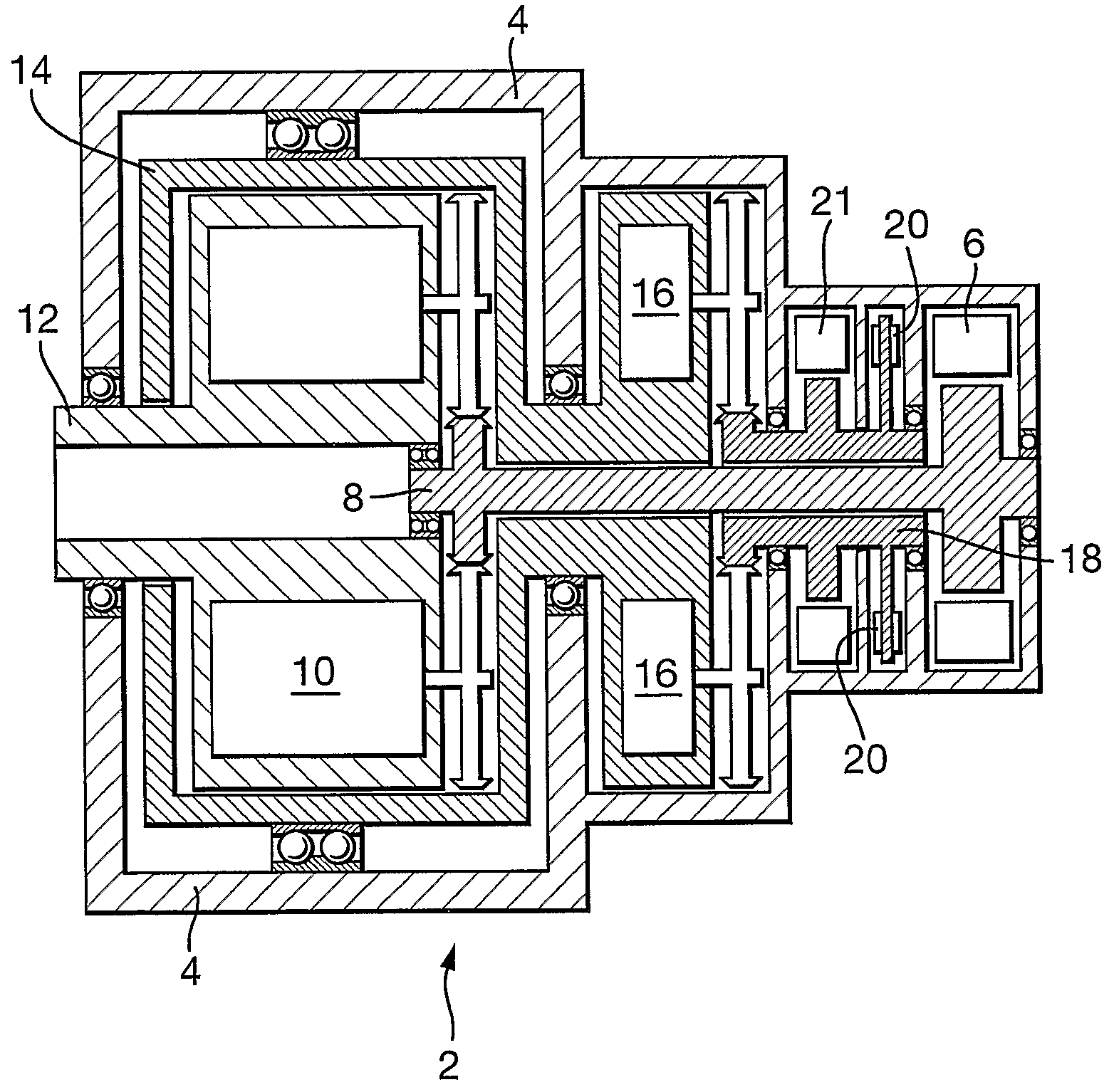
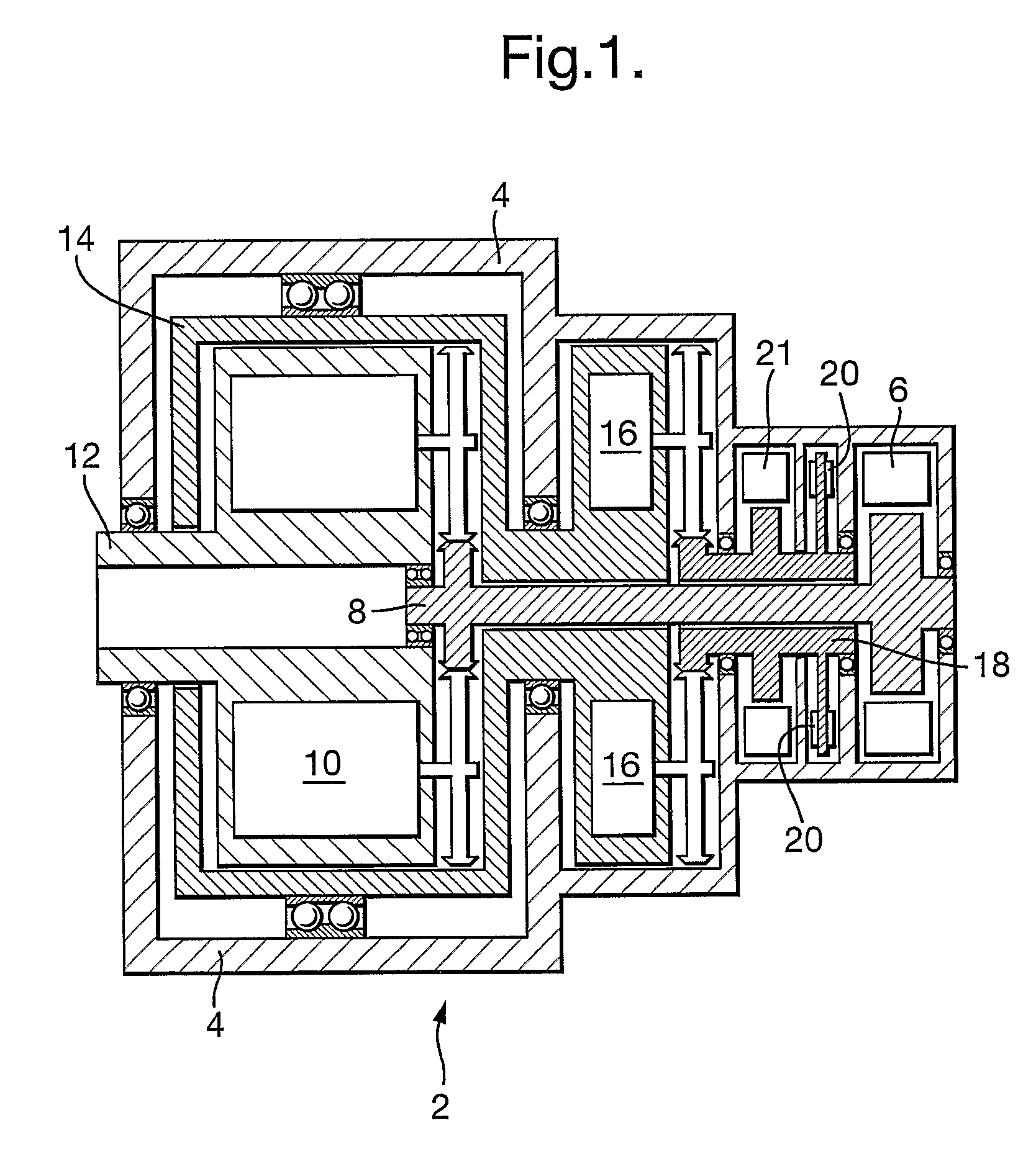
[0059]FIG. 1 illustrates the invention relating to a reconfigurable jam-tolerant electromechanical rotary actuator 2 for use as the steering actuator of a nose landing gear on a large commercial passenger aircraft. The actuator 2 comprises an outer housing 4 which is fixed to the adjacent aircraft structure (not shown). The actuator has two distinct modes of operation. The first mode of operation is the primary, and normal, mode of operation. The second mode of operation is a secondary, and back-up or emergency (such as free-castoring), mode of operation.

[0060]The actuator 2 houses an electric rotary motor 6 with a motor shaft 8 coupling the motor with a first gearbox 10. The electric motor is a bi-directional brushless DC motor, with fault-tolerant winding as necessary, able to generate a maximum torque of about 27 Nm. The first gearbox 10 converts the low torque high speed rotary motion from the motor 6 into high torque low speed motion which is output at a primary output shaft 12...

second embodiment

[0076]As a variant of the above-described second embodiment, the first and second gearboxes may have different ratios, so that the second gearbox is back-driveable. This may result in the output torque being reduced in the second mode of operation. Thus, in the event of a complete power failure, the brake would release the housing of the first gearbox and the clutch would couple the output shaft and the housing of the first gearbox (the clutch being configured so that the clutch applies in the event of loss of electric power). The output shaft could then be rotated, and would back-drive the second gearbox and the second motor. If the actuator were used to drive the steering of the nose landing gear, the aircraft could then be allowed to free-castor. Damping of that motion may be provided by means of adding an electro-mechanical damping mechanism.

[0077]The actuator may be supplied to move a component on the aircraft other than the nose landing gear.

[0078]The control unit may include ...


PUM


Abstract

An actuator, comprises a housing, a first prime mover for producing rotary motion, a first gearbox arranged to convert in use the rotary motion from the first prime mover into rotary motion having higher torque and lower speed. The first gearbox comprises a casing mounted for rotation relative to the housing of the actuator and a second gearbox arranged to convert rotary motion of the casing of the first gearbox into rotary motion having lower torque and higher speed.A brake is arranged to act on the rotary motion having lower torque and higher speed from the second gearbox. In use when the first gearbox is not jammed, the brake may be applied to resist relative rotation between the casing of the first gearbox and the housing of the actuator.When the first gearbox is jammed, the brake may be released thereby allowing the casing of the first gearbox to rotate relative to the housing of the actuator. The actuator may thereby be jam-tolerant. A second motor may also be provided.

Description

RELATED APPLICATIONS[0001]The present application is based on International Application Number PCT / GB2007 / 050495 filed Aug. 17, 2007, and claims priority from British Application Number 0616730.8, filed Aug. 23, 2006, the disclosures of which are hereby incorporated by reference herein in their entirety.BACKGROUND OF THE INVENTION[0002]The present invention relates to an actuator and in particular, but not exclusively, to a jam-tolerant electromechanical actuator for moving an aircraft component.[0003]Actuators may be used to cause movement of aircraft components such as the landing gear of an aircraft, for example steering the nose landing gear. Such actuators should of course be of high integrity and should have a very low risk of failure. For example, it is important for actuators to have at least two modes of operation so that there is for example a secondary, or emergency, mode of operation that facilitates movement of the aircraft component in the event of a loss of, or failur...

Claims


Application Information

Patent Timeline
Patent Type & Authority Patents(United States)
IPC IPC(8): B64C25/50B64C25/10B60W10/10B64C9/00
CPCB64C13/34F16H25/205F16H35/10Y10T477/38Y10T74/19121
Inventor ELLIOTT, NICHOLASDIDEY, ARNAUD
Owner AIRBUS OPERATIONS LTD
Why Eureka
Try Eureka