Ultra thin neutron detector, method for manufacturing the neutron detector and neutron imaging apparatus

a technology for neutron imaging and ultra-thin neutrons, which is applied in the direction of electrical devices, instruments, and neutron radiation measurement, can solve the problems of inaccurate measurement and undesired effects, and achieve the effects of excellent radiation hardness, fast charge collection, and reduced labor intensity

Active Publication Date: 2011-04-28
RAKKATEC OY
View PDF5 Cites 11 Cited by
  • Summary
  • Abstract
  • Description
  • Claims
  • Application Information

AI Technical Summary

Benefits of technology

[0014]An object of the invention is to alleviate the drawbacks related to the known prior art detectors. Especially an aim of the invention is to provide a detector, which is sensitive for detecting neutrons but at the same time “transparent” for the background gammas and / or X-rays. In addition a goal of the invention is to provide a detector with fast charge collection and with excellent radiation hardness.

Problems solved by technology

There are however some problems related to the known prior art solutions, namely since most of the neutron sources or reactions are accompanied by a gamma or X-ray background and because the neutral gamma or X-ray radiation interacts with the semiconductor matter of the detectors, the gamma or X-ray background will disturb the accurate measuring, which is an undesired effect especially in connection with neutron imaging apparatuses.

Method used


Image

  • Ultra thin neutron detector, method for manufacturing the neutron detector and neutron imaging apparatus
  • Ultra thin neutron detector, method for manufacturing the neutron detector and neutron imaging apparatus
  • Ultra thin neutron detector, method for manufacturing the neutron detector and neutron imaging apparatus

Examples


Embodiment Construction

I Detector Structure-Neutron Converter

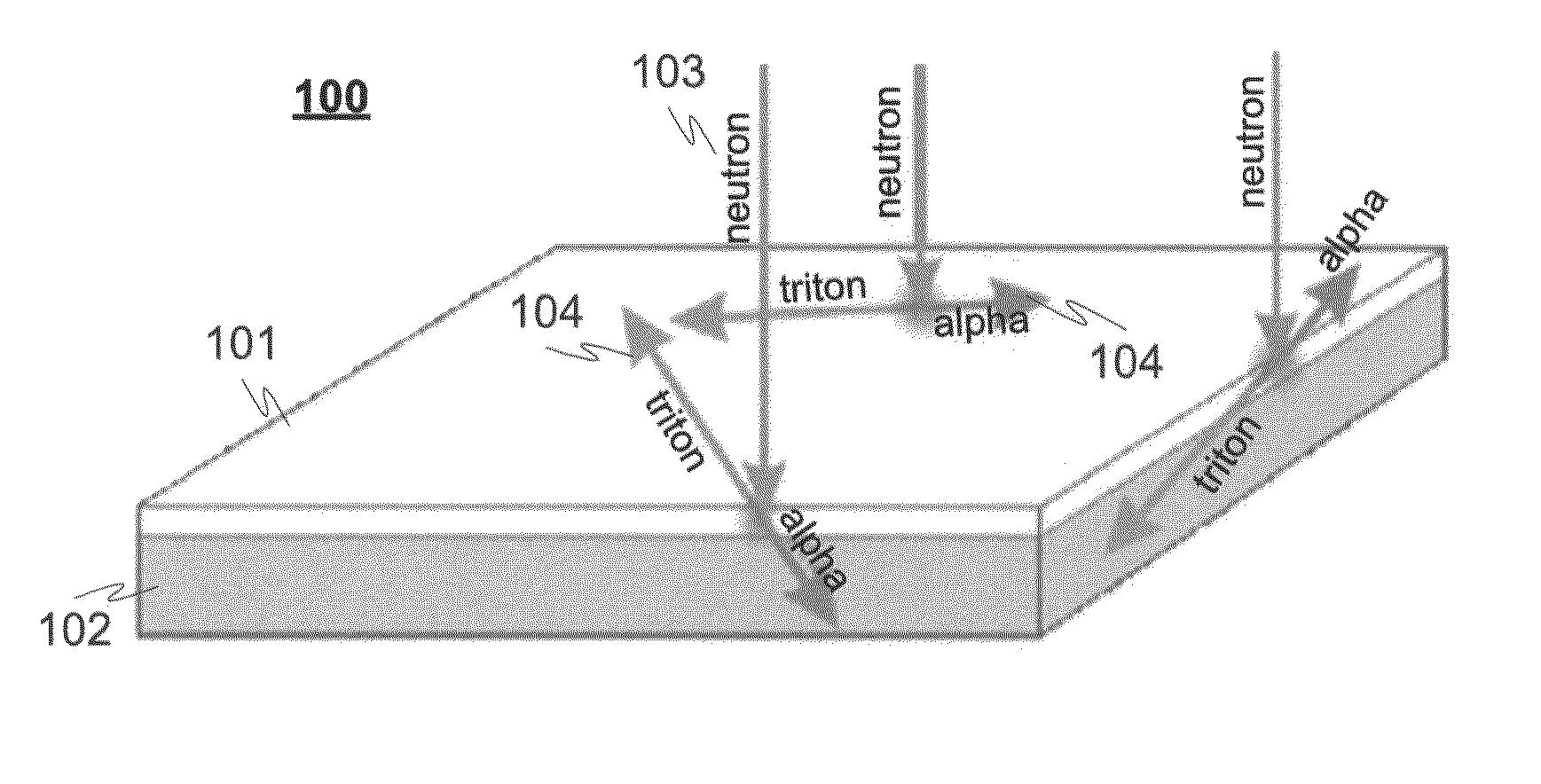
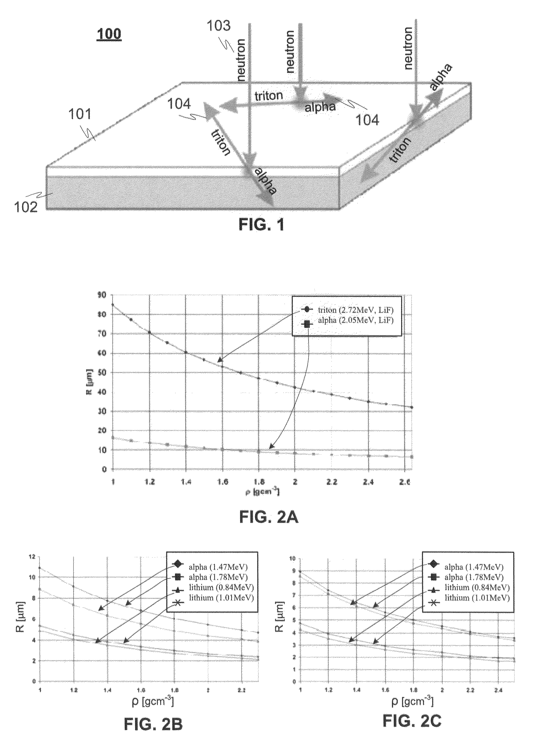
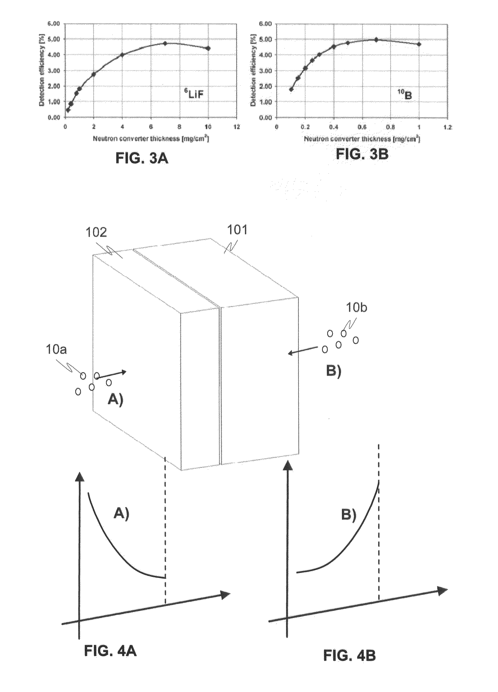
[0058]The semiconductor detectors (e.g. illustrated in FIGS. 1 and 10-16) are typically adapted for the thermal neutron detection and imaging, and are supplemented with a material (neutron reactive material) which “converts” neutrons into reaction products. The reaction products advantageously transfer its energy to charge carriers, which can be electrically detected directly in the semiconductor detector. Silicon is very commonly used in the detectors but there are besides silicon also other types of semiconductor materials which can be used, such as silicon carbide, germanium, gallium arsenide (GaAs), gallium phosphide, gallium nitride, indium phosphide, cadmium telluride (CdTe), cadmium zinctelluride (CdZnTe), mercuric iodide, lead iodide, and composite materials based on boron nitride (BN) or lithium fluoride (LiF). Their advantage is that the neutron converting material can be presented directly in their volume. For example silicon walls of...


PUM


Abstract

A detector (100) for detecting neutrons includes a neutron reactive material (102) adapted to interact with neutrons to be detected and release ionizing radiation reaction products in relation to the interactions with neutrons. The detector also includes a first semiconductor element (101) being coupled with the neutron reactive material (102) and adapted to interact with the ionizing radiation reaction products and provide electrical charges proportional to the energy of the ionizing radiation reaction products. In addition electrodes are arranged in connection with the first semiconductor element (101) for providing charge collecting areas (106) for collecting the electrical charges and to provide electrically readable signal proportional to the collected electrical charges. The thickness of the first semiconductor element (101) is adapted to be electrically and/or physically so thin that it is essentially/practically transparent for incident photons, such as background gamma photons.

Description

[0001]The file of this patent contains at least one drawing executed in color. Copies of this patent with color drawings will be provided by the Patent and Trademark Office upon request and payment of the necessary fee.TECHNICAL FIELD OF THE INVENTION[0002]The invention relates especially to a neutron detector, method for manufacturing said detector, and neutron imaging apparatus.BACKGROUND OF THE INVENTION[0003]Different kinds of detectors are known from the prior art for detecting, tracking, and / or identifying ionizing radiation and high-energy particles, such as particles produced by nuclear decay, cosmic radiation, or reactions in a particle accelerator. Some examples of ionizing radiation types and particles producing ionizing radiation via collisions with other particles are: Alpha particles (helium nuclei), beta particles (electrons), neutrons, gamma rays (high frequency electromagnetic waves, X-rays, are generally identical to gamma rays except for their place of origin), an...

Claims


Application Information

Patent Timeline
Patent Type & Authority Applications(United States)
IPC IPC(8): G01T3/08H01L31/18
CPCG01T3/08H01L31/1185H01L31/115
Inventor ORAVA, RISTOSCHULMAN, TOM
Owner RAKKATEC OY
Why Eureka
Try Eureka