Inspecting potentially interfering features in a machine vision system

a machine vision inspection and feature technology, applied in the field of machine vision inspection systems, can solve the problems of overlapping or interfering edges of some features, prior art methods for automatically inspecting such features are neither easy to program for unskilled users of the machine vision inspection system, nor robust enough to operate properly under a wide variety of conditions, so as to simplify training and programming for users, the effect of easy implementation

Active Publication Date: 2012-09-18
MITUTOYO CORP
View PDF8 Cites 16 Cited by
  • Summary
  • Abstract
  • Description
  • Claims
  • Application Information

AI Technical Summary

Benefits of technology

[0019]In some embodiments, the robust video tool comprises an excluded region mode wherein the excluded region operations are performed, and a non-excluded region mode comprising non-excluded region operations that analyze a workpiece image and determine a set of current-feature edge points such that the set of current-feature edge points includes edge points detected in the region of interest without consideration of an excluded region. In such cases, the robust video tool interface may include an excluded region activation element which is operable by a user to determine whether or not an instance of the robust video tool operates in the excluded region mode or the non-excluded region mode. Such a versatile robust video tool simplifies training and programming for users.
[0020]It will be appreciated that the features outlined above and disclosed in greater detail below may be particularly useful for certain applications. For example, in an implementation where the workpiece is a multiple layer workpiece (e.g., a printed circuit board including a solder resist layer), edge features in the various layers may overlap, causing conventional edge detection tools to fail or mislead due to “confusion” regarding which edge feature is in which layer and the inability to separate their respective edges. Conventional video tools have regions of interest that are unable to solve this problem, due to the fact that the features may truly overlap on some workpieces and not on others, such that the regions of interest cannot be programmed to reliably isolate a particular feature and operate effectively or reliably for all workpiece conditions. Similarly, known feature “masking” programming methods (e.g., see U.S. Pat. No. 7,324,682, which is hereby incorporated by reference in its entirety) are taught by assuming that an occluding or interfering feature is always present, and so may not operate effectively or reliably for all workpiece conditions. It should be appreciated that for some properly fabricated workpieces, there is no occlusion or overlap of features, and thus the methods of the '682 patent cannot even be programmed in learn mode, due to the absence of interfering or occluding elements in the region of interest of a “current feature” on a properly fabricated representative workpiece. Thus, the features associated with the present invention are more general, easier to implement, and yet more robust for certain types of applications, in comparison to the prior art. In particular, the features disclosed herein allow programming in learn mode on a representative workpiece, whether properly fabricated or improperly fabricated, and will still operate reliably in the resulting automatic part program on a run mode workpiece that is either properly fabricated or improperly fabricated.

Problems solved by technology

In some cases, these features may be contained in different layers and / or may interfere or have overlapping edges.
Such features may be concentric, or in some cases, fabrication errors may occur which cause the edges of some of the features to overlap or interfere.
Such errors may be associated with short circuiting or other problems for the operation of the PCB.
However, prior art methods for automatically inspecting such features are neither easy enough to program for unskilled users of the machine vision inspection system, nor robust enough to operate properly under a wide variety of possible alignments and misalignment conditions for the related features, which may potentially not overlap, or overlap to various degrees.

Method used


Image

  • Inspecting potentially interfering features in a machine vision system
  • Inspecting potentially interfering features in a machine vision system
  • Inspecting potentially interfering features in a machine vision system

Examples


Embodiment Construction

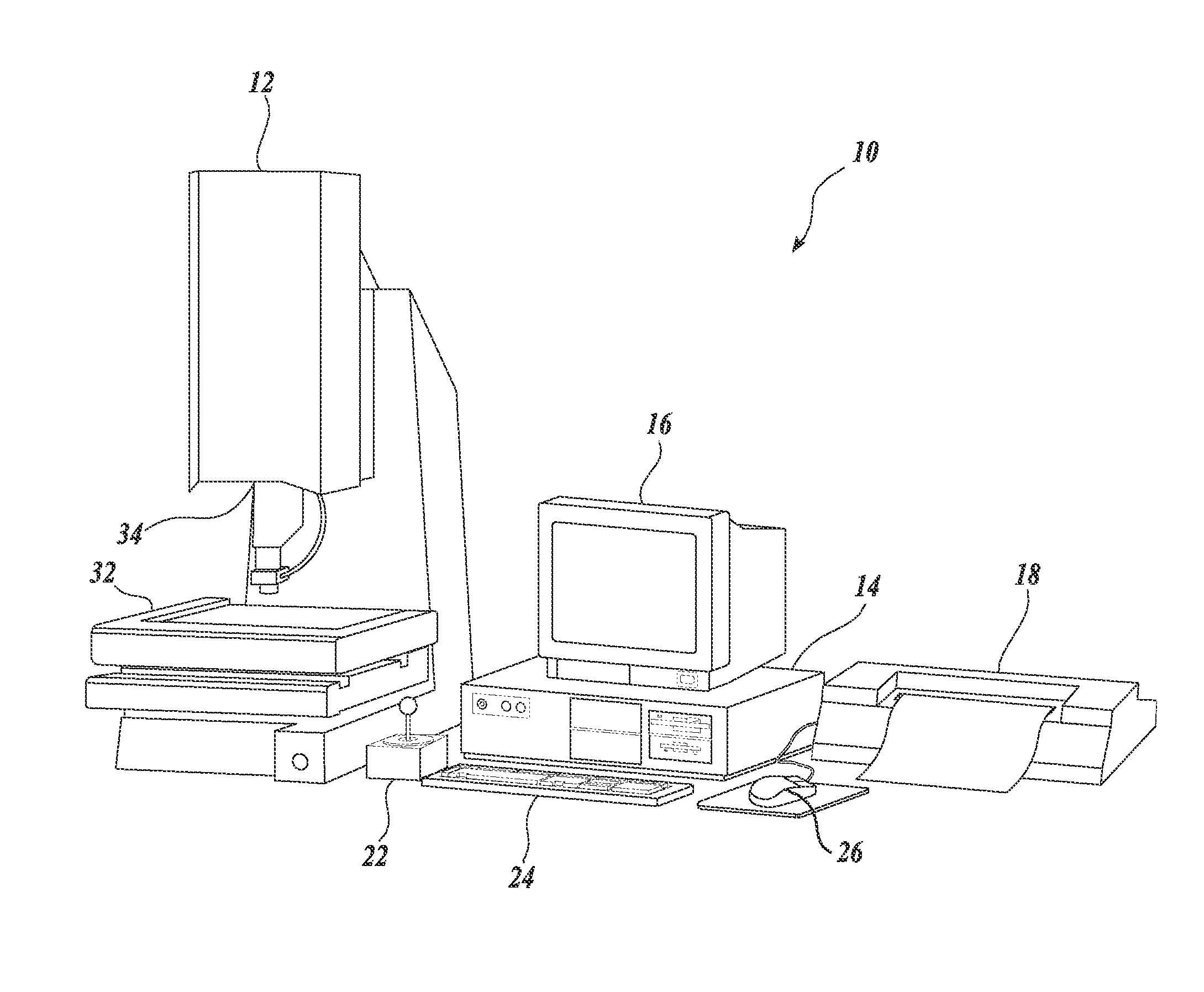
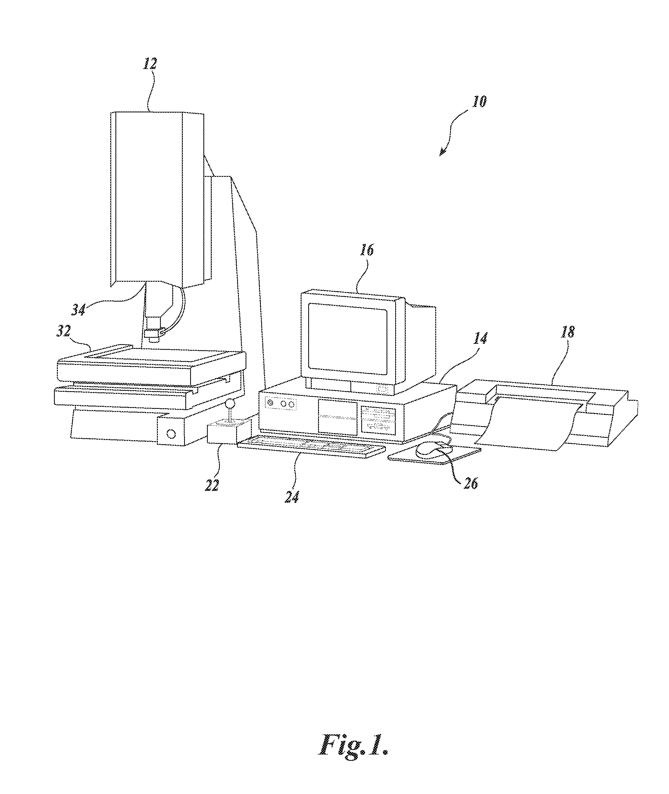
[0031]FIG. 1 is a block diagram of one exemplary machine vision inspection system 10 usable in accordance with methods described herein. The machine vision inspection system 10 includes a vision measuring machine 12 that is operably connected to exchange data and control signals with a controlling computer system 14. The controlling computer system 14 is further operably connected to exchange data and control signals with a monitor or display 16, a printer 18, a joystick 22, a keyboard 24, and a mouse 26. The monitor or display 16 may display a user interface suitable for controlling and / or programming the operations of the machine vision inspection system 10.

[0032]The vision measuring machine 12 includes a moveable workpiece stage 32 and an optical imaging system 34 which may include a zoom lens or interchangeable lenses. The zoom lens or interchangeable lenses generally provide various magnifications for the images provided by the optical imaging system 34. The machine vision insp...


PUM


Abstract

A robust video tool is provided for use in a machine vision inspection system. The robust video tool comprises a region of interest, a user interface, edge detection operations, and excluded region operations that determine a set of current-feature edge points which includes edge points detected in the region of interest and excludes edge points in an excluded region. The excluded region is determined by an excluded region generator, based on at least one previously characterized feature which is a feature characterized by using a video tool that detects the edge points of, and characterizes dimensional parameters of, the previously characterized feature. Importantly, the robust video tool features and operations are configured to allow learn mode programming on a workpiece that is either properly fabricated or improperly fabricated, and the resulting program will operate reliably on a run mode workpiece that is either properly fabricated or improperly fabricated.

Description

FIELD OF THE INVENTION[0001]The invention relates generally to machine vision inspection systems, and more particularly to methods of inspecting potentially interfering features on a workpiece.BACKGROUND OF THE INVENTION[0002]Precision machine vision inspection systems (or “vision systems” for short) can be utilized to obtain precise dimensional measurements of inspected objects and to inspect various other object characteristics. Such systems may include a computer, a camera and optical system, and a precision stage that is movable in multiple directions so as to allow the camera to scan the features of a workpiece that is being inspected. One exemplary prior art system that is commercially available is the QUICK VISION® series of PC-based vision systems and QVPAK® software available from Mitutoyo America Corporation (MAC), located in Aurora, Ill. The features and operation of the QUICK VISION® series of vision systems and the QVPAK® software are generally described, for example, i...

Claims


Application Information

Patent Timeline
Patent Type & Authority Patents(United States)
IPC IPC(8): H04N7/18
CPCG01N21/95684G06T7/001G01N21/8851G01N2021/646G01N2021/95638G01N2021/95646G01N2021/95661G01N2021/95669G06T2200/24G06T2207/10056G06T2207/20081G06T2207/30141
Inventor DELANEY, MARK LAWRENCE
Owner MITUTOYO CORP
Why Eureka
Try Eureka