

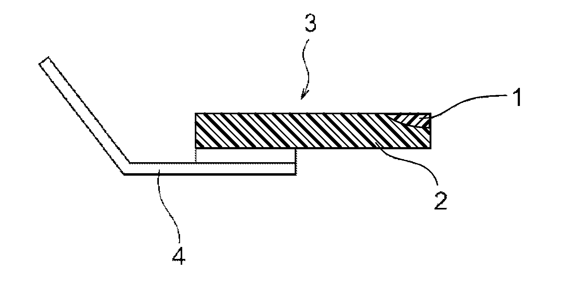
Blade for electrophotographic device with elastic rubber member constituted by edge/nip and base portions of different materials
a technology of electrophotography and elastic rubber, which is applied in the direction of electrographic process apparatus, instruments, optics, etc., can solve the problems of ether polyurethane being deemed unpractical and therefore not used, limiting the use of polyurethanes to a single material, and deteriorating pressure contact performance and physical properties. , to achieve the effect of low cos
- Summary
- Abstract
- Description
- Claims
- Application Information
AI Technical Summary
Benefits of technology
Problems solved by technology
Method used
Image

Examples
example
[0218]Cleaning blades or development blades were manufactured under the following conditions in the respective Examples and Comparative Examples.
[0219]For the manufacturing means, the method of continuous forming using a rotary forming drum with a groove formed on its outer periphery was used. Refer to FIG. 4 for the manufacturing apparatus.
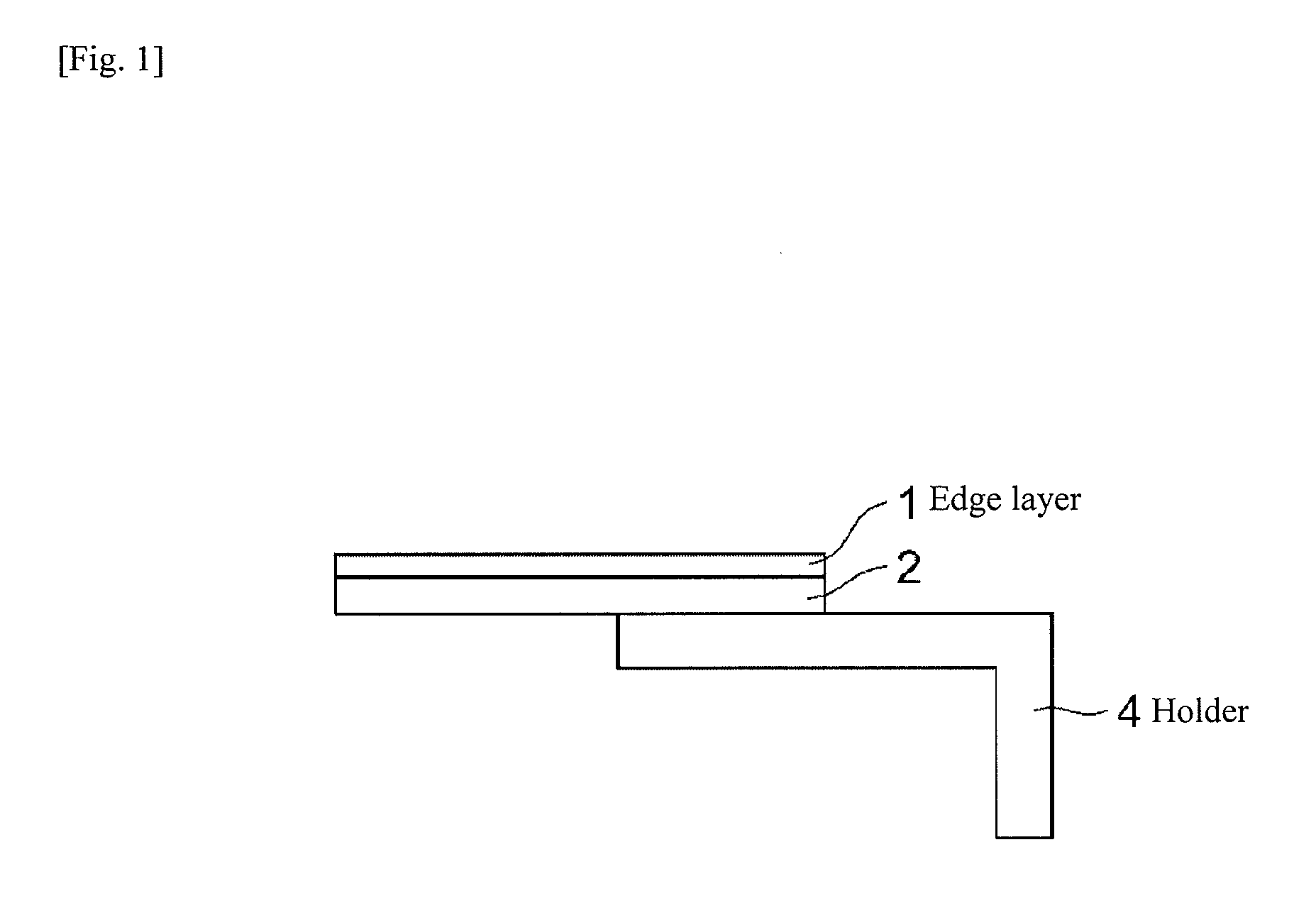
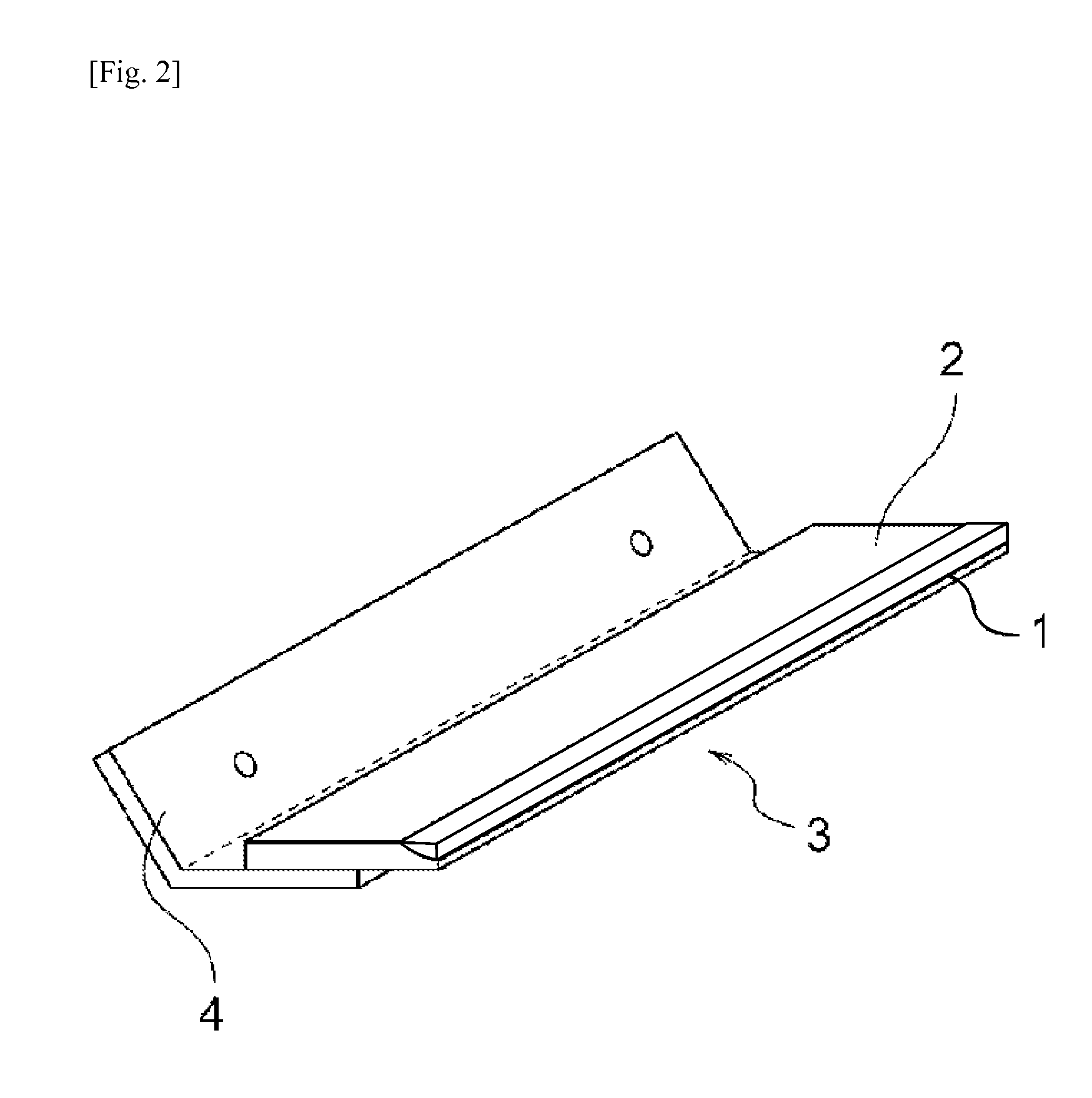
[0220]Polyurethane elastic rubber member: The thickness was 2.0 mm. The thickness of the edge layer (or nip layer) was 0.3 mm, while that of the base layer was 1.7 mm. The width and length were adjusted to an actual machine used in the test.
[0221]Metal support: Steel sheet of 1.2 mm in thickness
[0222]Bonding process: The above elastic rubber member and metal support were melt-bonded using hot-melt adhesive based on dimer acid.
[0223]The blends of ester urethanes and ether urethanes used for the edge (nip) layer and base layer are shown in each table.
[0224]The cleaning blade or development blade obtained from each Example or Comparative Example was...
examples 1 to 4
[0225]Tables 1 to 3 show the details of Examples 1 to 4 and Comparative Examples 1 to 4.
[0226]Table 1 shows the polyurethane compositions. Table 2 shows the physical properties and printing test results of Examples 1 to 3 and Comparative Examples 1 and 2 relating to cleaning blades. Table 3 shows the physical properties and printing test results of Example 4 and Comparative Examples 3 and 4 relating to development blades. The blades were tested in an actual machine after having been exposed for 14 days to a temperature of 43° C. and humidity of 95% following their forming. The physical properties represent those of polyurethanes before the test when the polyurethanes had been left for at least 7 days at room temperature following their forming and thus their physical properties were stable.
[0227]
TABLE 1Blends of Examples 1 to 4 and Comparative Examples 1 to 4In parts by weightEster typeEther typeBlend ABlend BBlend CBlend D(Hardness:(Hardness:(Hardness:(Hardness:Material65)77)65)77)...
examples 5 to 13
[0231]Table 4 shows the urethane blends, physical properties and evaluation test results of the cleaning blades obtained by Examples 5 to 13 and Comparative Examples 5.
[0232]The blades were tested in an actual machine after having been exposed for 14 days to a temperature of 43° C. and humidity of 95% following their forming. As is the case with Table 2, the physical properties represent those of polyurethanes before the test when their physical properties were stable.
[0233]
TABLE 4Example of cleaning bladeBlend for edge (Common to all examples)MaterialParts by weightBase resinMDI28.8HardenerPBA200064.9BD4.4TMP1.9Hardness74.0Impact resilience at 0° C.14Impact resilience at 23° C.25Impact resilience at 50° C.66Tanδ peak temperature7.0Blend for base (parts by weight)Exam-ExampleExampleExampleExampleComparativeMaterialple 5Example 6Example 7Example 8Example 910111213Example 5Base resinMDI34.334.334.333.336.132.337.132.336.128.8HardenerPPG100059.259.259.260.656.462.055.162.056.4PBA200064...
PUM
| Property | Measurement | Unit |
|---|---|---|
| temperatures | aaaaa | aaaaa |
| tan δ temperature | aaaaa | aaaaa |
| thickness | aaaaa | aaaaa |
Abstract
Description
Claims
Application Information