
Pneumatic fuel distributor for solid fuel boilers

a technology of solid fuel boilers and distributors, applied in the direction of combustion types, transportation and packaging, lighting and heating apparatus, etc., can solve the problems of poor operational efficiency, high environmental emissions, and inefficiently, and achieve the effect of improving fluid flow, efficient control of flow, and evenly distributing fuel

Inactive Publication Date: 2012-10-02
SULLIVAN HIGGINS & BRION PPE LLC
View PDF28 Cites 24 Cited by
  • Summary
  • Abstract
  • Description
  • Claims
  • Application Information

AI Technical Summary

Benefits of technology

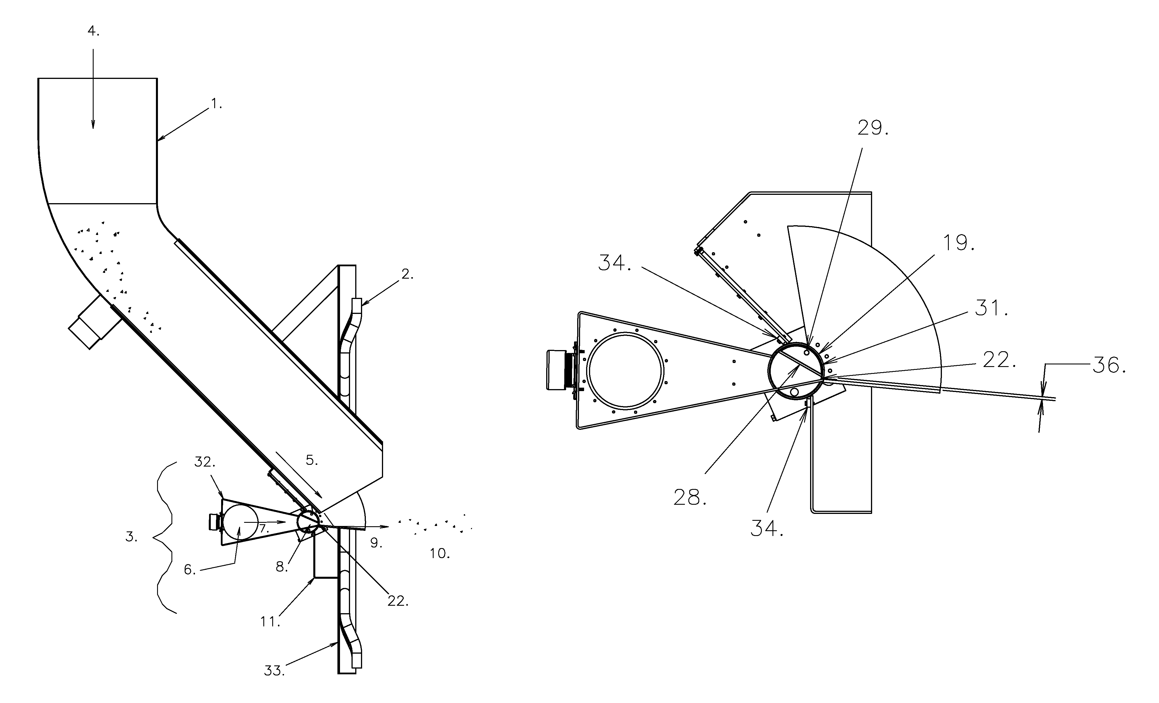
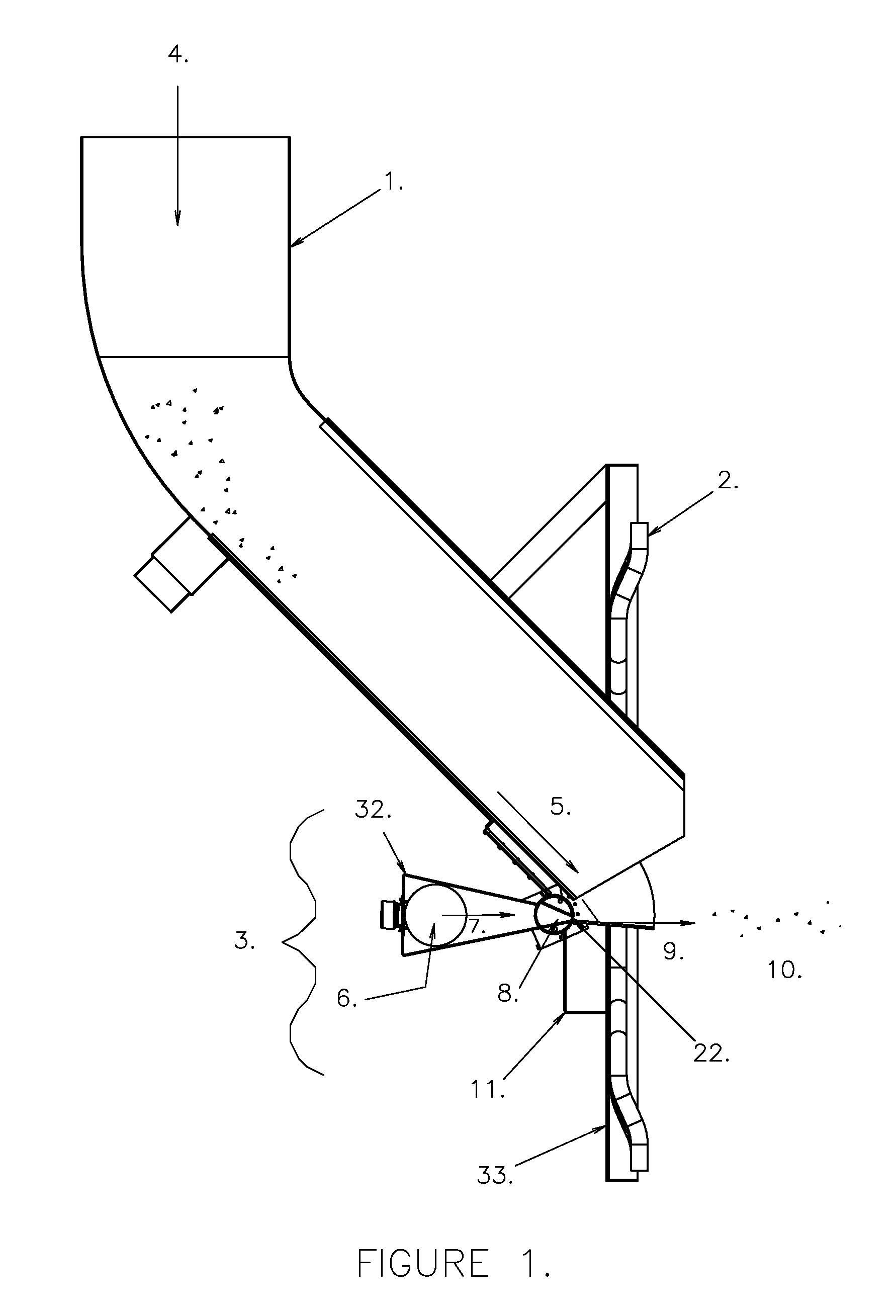
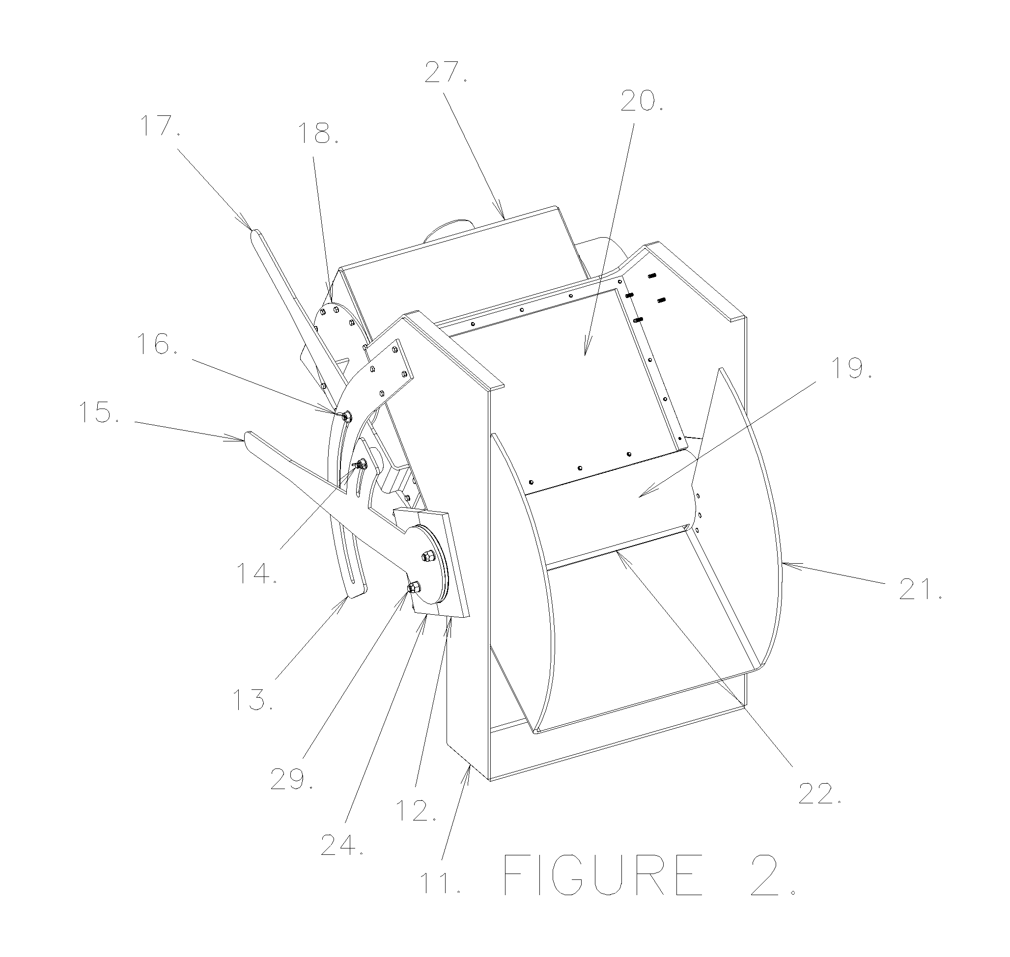
[0008]The present invention provides an improved fuel distributor for a solid fuel boiler. A preferred fuel distributor includes several novel aspects, not all of which need be present in all embodiments. Some embodiments of the invention use a converging nozzle section that provides improved fluid flow to distribute fuel more evenly. Some embodiments of the invention include an adjustable orifice that efficiently controls the flow at the exit of the nozzle, rather than upstream of the nozzle. Some embodiments include nozzle surfaces that converge toward the orifice to efficiently guide the pneumatic flow to and through the orifice. Some embodiments of the invention include an integral trajectory plate in which the nozzle, orifice and trajectory plate are all interconnected, preferably by a frame, and rotate together about a common axis. Some embodiments of the invention allow for easy removal of the distributor from the boiler. Some embodiments of the invention provide an access port that can be used to clean the unit in case it gets plugged and a viewing port that allows an operator to see into the distributor.

Problems solved by technology

In all of these arrangements if the fuel is not properly distributed on the grate or fluidized bed, poor combustion can result leading to poor operational efficiencies and high environmental emissions.
Grate type boilers generally require some type of fuel distribution whereas fluidized bed boilers can be run without them as the fluidized bed can distribute the fuel, albeit inefficiently.

Method used


Image

  • Pneumatic fuel distributor for solid fuel boilers
  • Pneumatic fuel distributor for solid fuel boilers
  • Pneumatic fuel distributor for solid fuel boilers

Examples


Embodiment Construction

[0017]Although pneumatic solid fuel distributors have been in service for many years, applicants have found that the current state of the art suffers from significant deficiencies, including poor control of the fluid media; poor nozzle design; poor alignment of the pneumatic nozzle, orifice, and trajectory plate; poor serviceability and maintenance access; and poor observational access.

[0018]Although prior art mechanical and pneumatic fuel distributors improve the operation of the boiler, Applicants have found that current pneumatic distributors have several deficiencies. First, current designs have a poor orifice that does not efficiently control the flow of the pneumatic media. They either have a fixed orifice opening with an upstream damper to control the flow or an adjustable orifice poorly designed fluid dynamically. This results in high flow losses, high pressures required upstream, and / or higher flows required. Second, current designs generally have poorly designed nozzles or...


PUM


Abstract

A pneumatic fuel distributor for solid fuel boilers is described incorporating in various embodiments one or more of the following features: a converging nozzle section, a converging adjustable orifice section and an integral trajectory plate. The nozzle, orifice and trajectory plate are preferably all interconnected and rotate together about a common axis. The orifice damper is, in one embodiment, a rotating convergent section and independently adjustable. The unit preferably incorporates a viewing glass and access port and the rotating components are preferably removable for maintenance. The unit is preferably reversible for left or right hand installation and the trajectory plate is easily replaceable.

Description

[0001]This application claims priority from U.S. Provisional Patent Application No. 61 / 037,169, which is hereby incorporated by reference.TECHNICAL FIELD OF THE INVENTION[0002]The present invention relates to fuel distributors for solid fuel boilers.BACKGROUND OF THE INVENTION[0003]Pneumatic solid fuel distributors are well known in the operation of boilers to improve the distribution of fuel in the boiler. They typically feed bark, “hog fuel” (mixtures of bark and cardboard, sludge, or other waste materials), coal, and / or other solid fuels, separately or combined. They are also referred to as “bark distributors” or “wind swept spouts”. Common designs incorporate a nozzle section (fixed or pivoting) and a pivoting trajectory plate to adjust the angle at which the solid fuel is injected into the boiler. The trajectory plate pivots about a horizontal axis thereby controlling the vertical angle at which the fuel is injected. A more recent design incorporates a flexible trajectory plate...

Claims


Application Information

Patent Timeline
IPC IPC(8): F23K3/18F23K3/02F23L13/00
CPCF23C9/00F23D1/00F23K3/02F23M7/02F23M11/042F23D2201/101F23D2201/20
Inventor HIGGINS, DANIEL RICHARDSULLIVAN, EUGENE
Owner SULLIVAN HIGGINS & BRION PPE LLC
Learn More