Supercharge Your Innovation With Domain-Expert AI Agents!

Froth flotation method and apparatus, a froth flotation method and apparatus for extracting bitumen from a slurry of water and oil sand, and use of the apparatus

a technology of froth flotation and slurry, which is applied in the direction of flotation treatment, solid separation, petroleum industry, etc., can solve the problems of inefficiency in separation, impurities, and slurry and liquid pockets entrainmen

Active Publication Date: 2012-10-02
METSO OUTOTEC (FINLAND) OY
View PDF9 Cites 5 Cited by
  • Summary
  • Abstract
  • Description
  • Claims
  • Application Information

AI Technical Summary

Benefits of technology

The present invention provides a new and improved froth flotation method for extracting valuable substances from a slurry of solid phase, liquid phase, and substance. The method includes delivering gas bubbles into the slurry, agitating the slurry to disperse the gas bubbles, and forming negative pressure zones in the froth phase to capture unwanted slurry and liquid pockets. The negative pressure zones are generated by mechanically generating continuously moving negative pressure zones in the froth phase before the overflow. The invention has the advantage of reducing the entrainment of unwanted slurry into the froth phase, improving separation efficiency. The apparatus includes a flotation vessel with means for mechanically generating the negative pressure zones, such as sloped rake blades or a helical rotor with rake blades. The invention is particularly useful for extracting bitumen from oil sand.

Problems solved by technology

In the known methods and apparatuses there is a common problem of the entrainment of slurry and liquid pockets, i.e. impurities, from the slurry phase into froth phase.
These impurities may exit from the flotation vessel together with the froth overflow causing inefficiency in separation.

Method used


Image

  • Froth flotation method and apparatus, a froth flotation method and apparatus for extracting bitumen from a slurry of water and oil sand, and use of the apparatus
  • Froth flotation method and apparatus, a froth flotation method and apparatus for extracting bitumen from a slurry of water and oil sand, and use of the apparatus
  • Froth flotation method and apparatus, a froth flotation method and apparatus for extracting bitumen from a slurry of water and oil sand, and use of the apparatus

Examples


Embodiment Construction

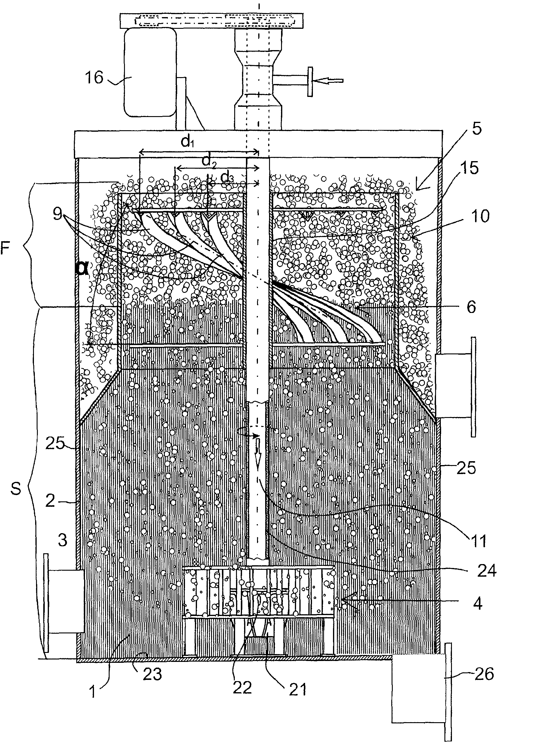
[0029]FIG. 1 shows a froth flotation apparatus configured to process slurry 1 in order to extract a valuable substance, such as minerals or oil in the form of bitumen or the like, from the slurry. A special use of the apparatus to which, however, the apparatus is not limited is in the field of extracting bitumen bound in the oil sand grains from a slurry which is a mixture of oil sand as the solid phase and water as the liquid phase.

[0030]The flotation apparatus comprises flotation vessel 2 formed by side walls 25 and a bottom wall 23. The inlet 3 is arranged at the side wall 25 for feeding slurry 1 into the vessel 2. The apparatus also includes an outlet 26 for discharging the processed slurry and sludge. The apparatus further includes gas dispersion mechanism 4 arranged to feed gas, for example air, into the slurry to infuse gas bubbles into the slurry. In FIG. 1 the slurry 1 and the slurry phase S are shown with vertical hatching. The bubbles rise above the surface of the slurry ...


PUM

PropertyMeasurementUnit
helix anglesaaaaaaaaaa
pressureaaaaaaaaaa
radial distancesaaaaaaaaaa

Abstract

A froth flotation method and apparatus for extracting a valuable substance from a slurry comprising a mixture of solid phase, liquid phase and said substance. A gas dispersing mechanism (4) feeds gas into the slurry (1) in a flotation vessel (2) to infuse gas bubbles into the slurry. The slurry is agitated in the flotation vessel (2) for dispersing the gas bubbles into the slurry. The gas bubbles capture the valuable substance from the slurry and form a froth phase F above the slurry phase S. The froth phase F exits the vessel by overflow. Continuously moving negative pressure zones (7) are mechanically generated by rake blades (9) in the froth phase (F). The negative pressure zones (7) extend from the froth phase (F) to the slurry phase (S). The negative pressure zones (7) capture unwanted slurry and liquid pockets (8) entrained from the slurry phase to the froth phase (F) and form paths for guiding said unwanted slurry and liquid pockets (8) via said paths from the froth phase (F) downwardly back to the slurry phase (S).

Description

CROSS-REFERENCE TO RELATED APPLICATION[0001]This application claims benefit under 35 USC 119 of Provisional Application No. 61 / 094,469 filed Sep. 5, 2008.FIELD OF THE INVENTION[0002]The present invention relates to a froth flotation method and apparatus and its use. In particular, the present invention relates to a novel and improved method and apparatus for extracting bitumen from a slurry of water and oil sand containing bitumen.BACKGROUND OF THE INVENTION[0003]In conventional flotation methods and apparatuses a valuable substance is extracted from a slurry comprising a mixture of solid phase, liquid phase and said substance. Gas is fed into the slurry in a flotation vessel to infuse gas bubbles into the slurry while the slurry is agitated in the flotation vessel for dispersing the gas bubbles into the slurry. When the particles of the valuable substance come to contact with the gas bubbles they are attached to the bubbles and rise upwards to the surface of the slurry to form a fo...

Claims


Application Information

Patent Timeline
Patent Type & Authority Patents(United States)
IPC IPC(8): B03D1/14B03D1/16C10G1/00B03D1/20C10G1/04
CPCB03D1/22B03D1/1462C10G1/045C10G1/047C10G1/04C02F1/24
Inventor KUJAWA, CHRISTIAN
Owner METSO OUTOTEC (FINLAND) OY
Features
  • R&D
  • Intellectual Property
  • Life Sciences
  • Materials
  • Tech Scout
  • Unparalleled Data Quality
  • Higher Quality Content
  • 60% Fewer Hallucinations
Learn More