

Flow-separation back-mixing-free spraying tower disc
A tray and back-mixing technology, which is applied in the field of mass transfer equipment and heat transfer, to achieve the effects of improving mass transfer driving force and tray efficiency, uniform liquid level, and improving gas-liquid separation efficiency
- Summary
- Abstract
- Description
- Claims
- Application Information
AI Technical Summary
Problems solved by technology
Method used
Image

Examples
Embodiment 1
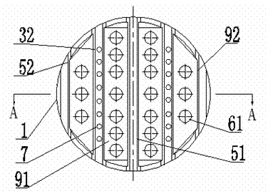
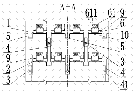
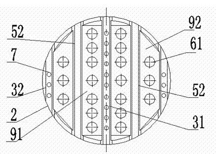
[0042] Design a split-flow non-backmixing jet tray (see Figure 1-4 ), the tray is composed of the upper tray 1 and the lower tray 2, the upper tray 1 includes 2 downcomers 32, 16 downcomers 4, 1 central liquid receiver 51 and 2 other receivers Liquid tank 52, 4 sets of three-dimensional jet mass transfer units 6, 2 sets of central liquid guide tank 91 and 2 sets of other liquid guide tanks 92; the lower tray 2 includes 3 downcomers 3, 16 downcomers 4, 2 Liquid receiving tank 5, 4 groups of three-dimensional jet mass transfer units 6, 2 groups of central liquid guiding tank 91 and 2 groups of other liquid guiding tanks 92; downcomer 3 and liquid receiving tank 5 adopt rectangular groove structure; Bobbin structure; the three-dimensional jet mass transfer unit 6 is a new vertical sieve plate.
[0043] Its working principle and process are: the liquid after mass transfer from the upper set of trays falls into the liquid receiving tank 5 in this set of trays through the downcome...
Embodiment 2
[0045] Design a split-flow non-backmixing jet tray (see Figure 5-6 ), the difference is that on the basis of the main structure of Example 1, a strip-shaped liquid level balance tank 8 is provided in the middle position of the tray in a direction perpendicular to the liquid receiving plate, and the liquid level balance tank 8 It is connected with the downcomer 3; its working principle is basically the same as that of Embodiment 1, because the liquid level balance tank 8 is provided, and the liquid level balance tank 8 is connected with the downcomer 3, so that each end of the downcomer can be After the liquid in the tank 3 is collected in the liquid level balance tank 8, it is evenly distributed to each downcomer tank 3, so that the liquid is evenly distributed and the liquid level gradient is reduced. This structure is more suitable for cases where the tower diameter is larger than DN3000.
Embodiment 3
[0047] Design a split-flow non-backmixing jet tray (see Figure 7 ), the tray structure is basically the same as that of Example 2, the difference is that the liquid level balance tank 8 is connected to the liquid receiving tank 5; the working principle is: the liquid level balancing tank 8 is connected to the liquid receiving tank 5, so that each end can be After the liquid in the liquid tank 5 is collected in the liquid level balance tank 8, it is evenly distributed to each liquid receiving tank 5, so that the liquid is evenly distributed, which is beneficial to reduce the gradient of the liquid level.
[0048] What is not mentioned in the present invention is applicable to the prior art.
PUM
| Property | Measurement | Unit |
|---|---|---|
| Depth | aaaaa | aaaaa |
| Width | aaaaa | aaaaa |
Abstract
Description
Claims
Application Information