Hydraulic cylinder

a technology of hydraulic cylinder and cylinder head, which is applied in the direction of brake systems, machines/engines, transportation and packaging, etc., can solve the problems of short distance between the fluid and the portion made up of the minute clearance, and achieve the effect of suppressing the occurrence of cavitation, suppressing the protrusion of the lip, and suppressing the fitting of the tip end of the lip

Inactive Publication Date: 2012-10-02
NOK CORP
View PDF7 Cites 6 Cited by
  • Summary
  • Abstract
  • Description
  • Claims
  • Application Information

AI Technical Summary

Benefits of technology

[0011]It is an object of the present invention to provide a hydraulic cylinder capable of suppressing occurrence of cavitation near a tip end of a lip of a seal member while protecting the tip end of the lip.
[0014]This will be described more specifically. Cavitation is a phenomenon in which part of liquid evaporates to form bubbles when flow velocity of a fluid is extremely high and pressure of the part of the liquid falls below saturation pressure for the liquid temperature and then the bubbles collapse. Because the flow velocity of the fluid is high in the minute clearance, the cavitation is likely to occur in this portion. However, if an axial distance of the portion made up of the minute clearance is shortened, a distance which the fluid flows through the portion made up of the minute clearance becomes short. Therefore, the fluid does not go as far as to form the bubbles while it flows through the portion made up of the minute clearance. In this way, it is possible to suppress occurrence of the cavitation.
[0016]More specifically, according to the present invention, there is provided the hydraulic cylinder including a cylinder having a shaft hole, a piston inserted into the shaft hole, and a seal member mounted in an annular mounting groove formed in an inner periphery of the shaft hole to seal an annular clearance between the inner periphery of the shaft hole and the piston, the seal member including a lip extending in an axial direction to slide against the piston, and a portion on a side of a lip tip end of the annular clearance between the inner circumferential face of the shaft hole and the piston being made up of a minute clearance in order to suppress protrusion of the lip, wherein an annular clearance area for suppressing occurrence of cavitation and for shortening an axial distance of the annular clearance portion made up of the minute clearance is formed on an opposite side of the annular clearance portion from the mounting groove.
[0017]In addition, according to the present invention, there is provided the hydraulic cylinder including a cylinder having a shaft hole, a piston inserted into the shaft hole, and a seal member mounted in an annular mounting groove formed in an inner periphery of the shaft hole to seal an annular clearance between the inner periphery of the shaft hole and the piston, the seal member including a lip extending in an axial direction to slide against the piston, wherein a small-diameter groove adjacent to the mounting groove and having a smaller diameter than the mounting groove is formed on a side of a lip tip end while leaving an annular clearance between the piston and the small-diameter groove having such a width as not to cause the cavitation and an annular member is mounted on a small-diameter groove side in the mounting groove so that an annular clearance between the piston and the annular member is a minute clearance in order to suppress protrusion of the lip and that an axial distance of the minute clearance is short.
[0018]Further, according to the present invention, there is provided the hydraulic cylinder including a cylinder having a shaft hole, a piston inserted into the shaft hole, and a seal member mounted in an annular mounting groove formed in an inner periphery of the shaft hole to seal an annular clearance between the inner periphery of the shaft hole and the piston, the seal member including a lip extending in an axial direction to slide against the piston, wherein an annular member is mounted on a side of a lip tip end in the mounting groove, a portion near the tip end of the lip of an annular clearance between an inner circumferential face of the annular member and the piston is made up of a minute clearance in order to suppress protrusion of the lip, and an annular clearance area for suppressing occurrence of cavitation and for shortening an axial distance of the annular clearance portion made up of the minute clearance is formed on an opposite side of the annular clearance portion from the seal member in an inner periphery of the annular member.
[0019]As described above, according to the invention, it is possible to suppress occurrence of the cavitation near the tip end of the lip while protecting the tip end of the lip of the seal member.

Problems solved by technology

However, if an axial distance of the portion made up of the minute clearance is shortened, a distance which the fluid flows through the portion made up of the minute clearance becomes short.

Method used


Image

  • Hydraulic cylinder
  • Hydraulic cylinder
  • Hydraulic cylinder

Examples


first embodiment

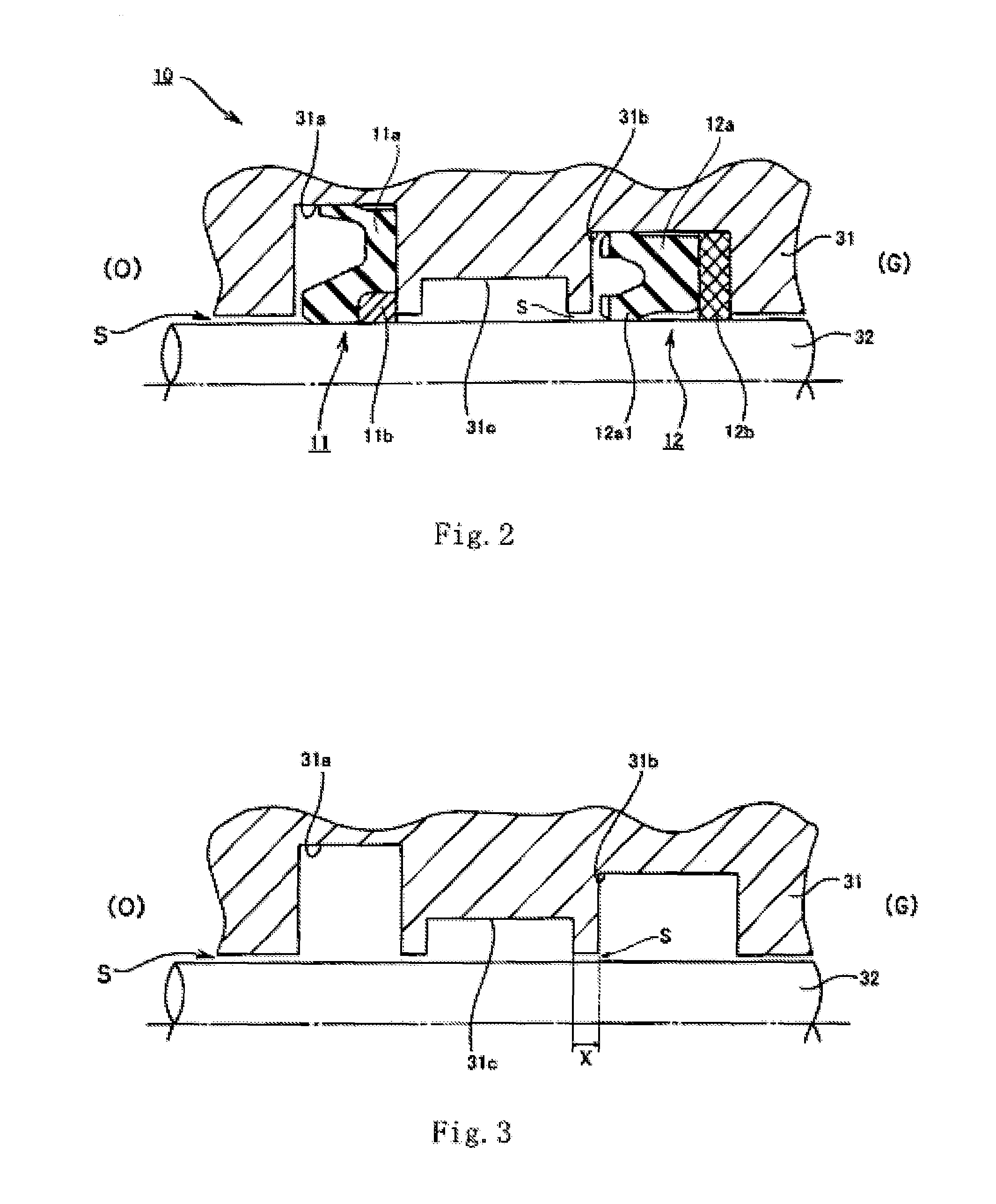
[0034]With reference to FIGS. 2 and 3, a first sealing system 10 in a hydraulic cylinder according to the first embodiment of the invention will be described. FIGS. 2 and 3 are schematic sectional views of an area where the first sealing system is provided in the hydraulic cylinder. FIG. 2 shows a state in which various seals are mounted and FIG. 3 shows a state in which the various seals are not mounted.

[0035]The first sealing system 10 includes a buffer ring 11 and a packing 12 as a seal member. The buffer ring 11 has a buffer ring main body 11a having a substantially U sectional shape and a backup ring 11b for preventing the buffer ring main body 11a from protruding into a minute clearance S (clearance) at an inner circumferential end portion on a low-pressure side (gas side (G)).

[0036]The packing 12 similarly has a packing main body 12a having a substantially U sectional shape and a backup ring 12b for preventing the packing main body 12a from protruding into a minute clearance ...

second embodiment

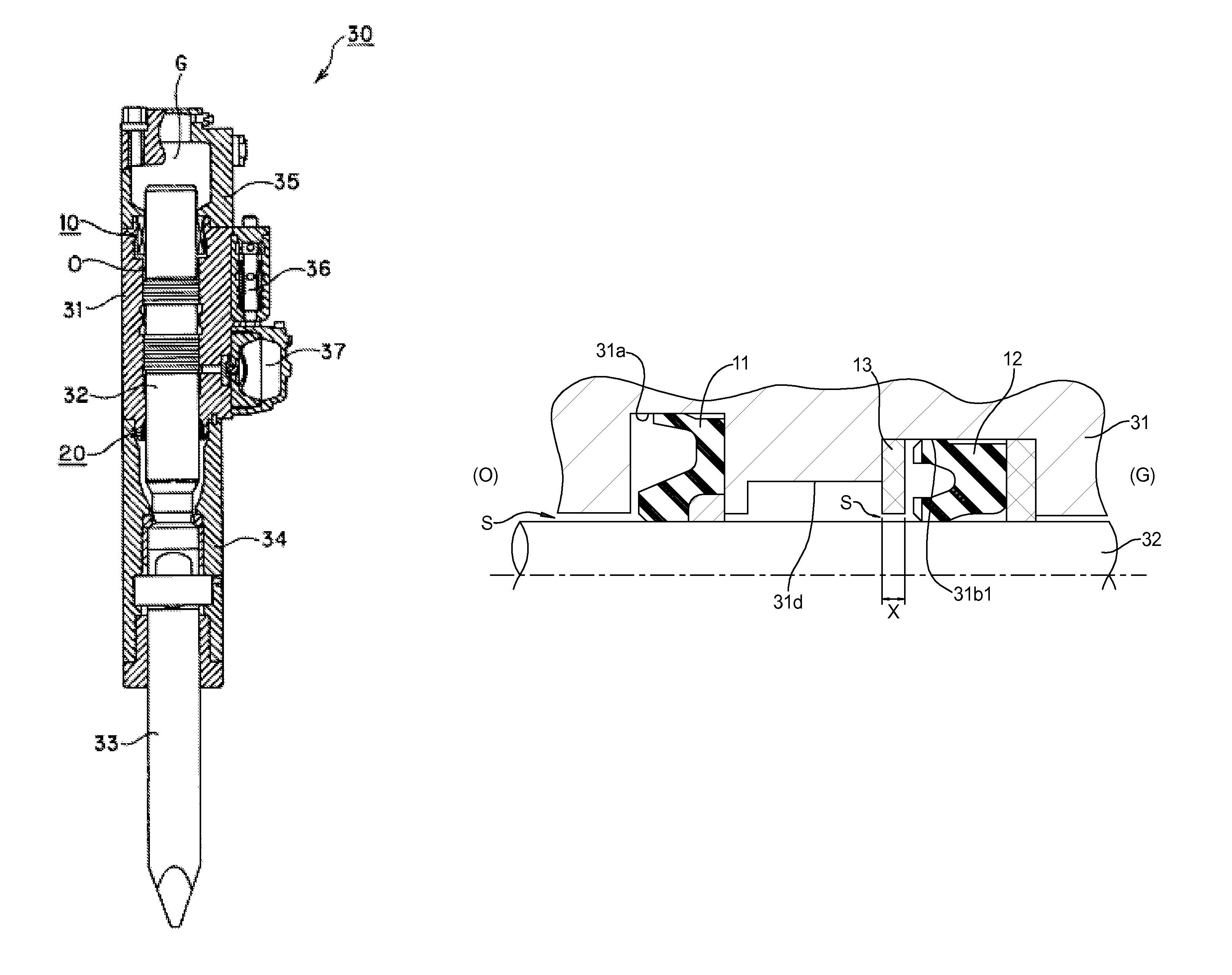
[0044]With reference to FIG. 4, a first sealing system in a hydraulic cylinder according to the second embodiment of the invention will be described. Basic structures are the same as those in the first embodiment and component portions having the same basic structures as those in the first embodiment will be provided with the same reference numerals and will not be described. Because structures of the buffer ring 11 and the packing 12 are the same as those in the first embodiment, they are shown in simple illustrations in FIG. 4.

[0045]In the present embodiment, the annular mounting grooves 31a and 31b1 are similarly formed in the inner periphery of the shaft hole formed in the cylinder 31. The buffer ring 11 and the packing 12 are respectively mounted in the mounting grooves 31a and 31b1.

[0046]In the embodiment, a small-diameter groove 31d adjacent to the mounting groove 31b1 and having a smaller diameter than that of the mounting groove 31b1 is formed while leaving an annular clear...

third embodiment

[0049]With reference to FIG. 5, a first sealing system in a hydraulic cylinder according to the third embodiment of the invention will be described. Basic structures are the same as those in the first embodiment and component portions having the same basic structures as those in the first embodiment will be provided with the same reference numerals and will not be described. Because structures of the buffer ring 11 and the packing 12 are the same as those in the first embodiment, they are shown in simple illustrations in FIG. 5.

[0050]In the present embodiment, the annular mounting grooves 31a and 31b2 are similarly formed in the inner periphery of the shaft hole formed in the cylinder 31. The buffer ring 11 and the packing 12 are respectively mounted in the mounting grooves 31a and 31b2.

[0051]In the embodiment, an annular member 14 made of resin is mounted on an oil side (O), i.e., on a side of a tip end of the lip 12a1 (not shown in FIG. 5) in the mounting groove 31b2. The annular ...


PUM


Abstract

The hydraulic cylinder having a portion on a side of a lip tip end of an annular clearance between an inner circumferential face of a shaft hole of a cylinder and a piston is made up of a minute clearance in order to suppress protrusion of the lip, wherein an annular clearance area for suppressing occurrence of the cavitation and for shortening an axial distance of the annular clearance portion made up of the minute clearance is formed on an opposite side of the annular clearance portion from a mounting groove.

Description

BACKGROUND OF THE INVENTION[0001]1. Field of the Invention[0002]The present invention relates to a hydraulic cylinder.[0003]2. Description of the Related Art[0004]In general, the hydraulic cylinder includes a piston, a cylinder, and a seal member for sealing an annular clearance between them. In the hydraulic cylinder, a piston is inserted into a shaft hole formed in the cylinder while leaving a minute clearance between an inner circumferential face of the shaft hole and the piston.[0005]In a hydraulic cylinder such as that used for a breaker in which the piston and the cylinder relatively reciprocate at high speed and which is used in an environment of high hydraulic pressure, cavitation occurs in the minute clearance.[0006]If the cavitation occurs, a cavitation shock wave or the like due to collapse of a bubble instantaneously generates extremely high pressure around a position where the cavitation has occurred. As a result, if the cavitation occurs near a lip of a seal member mou...

Claims


Application Information

Patent Timeline
Patent Type & Authority Patents(United States)
IPC IPC(8): F16J15/18F16J15/32F15B15/14
CPCF15B15/1461F15B21/047F16J15/164F16J15/3236
Inventor ABE, YOSHIYUKI
Owner NOK CORP
Why Eureka
Try Eureka