Wave power plant

a technology for wave power plants and apparatuses, applied in water-power plants, machines/engines, electric generator control, etc., can solve the problems of low efficiency and mass set in motion, and achieve the effect of increasing the efficiency of wave power collection apparatuses, increasing the efficiency of wave energy collectors, and increasing the efficiency of apparatuses

Active Publication Date: 2012-10-02
LANGLEE WAVE POWER
View PDF48 Cites 5 Cited by
  • Summary
  • Abstract
  • Description
  • Claims
  • Application Information

AI Technical Summary

Benefits of technology

[0013]The fluidity of the water and pressure front that hits the barrier in the form of a panel or a sail in an energy collecting apparatus will also to a certain extent be deflected via loss / avoidance to the side of the barrier. This consideration has not been taken into account earlier, but helps to raise the efficiency of the wave power collecting apparatus that is driven via collection of horizontally moving pressure fronts.
[0014]To solve this problem and increase the efficiency of an apparatus according to the present invention, it is preferred to equip the apparatus with essentially vertical side walls that extend either partly or fully across the working area of the tilting barrier. This will be explained in greater detail below with reference to specific embodiments of the invention. Such side walls will also help to increase the efficiency of wave energy collectors positioned completely below the water surface.

Problems solved by technology

This is the reason that wave collectors which work via a tilting action, and which are located on the bottom of the sea with a large amount of water above the apparatus, will achieve very low efficiency because the energy of the wave will flow over and alongside the barrier in the form of a panel more or less unobstructed and thus retain its energy instead of transferring it to the barrier in the form of a panel.
The positioning of a moving object (for example, a tilting barrier in the form of a panel) close to the surface of the liquid will, however, result in the mass set in motion by the passing wave only having the possibilities of either being reflected by the barrier in the form of a panel, or being refracted by the barrier in the form of a panel (depending on whether the wave can move past the panel or not).

Method used


Image

  • Wave power plant
  • Wave power plant
  • Wave power plant

Examples


Embodiment Construction

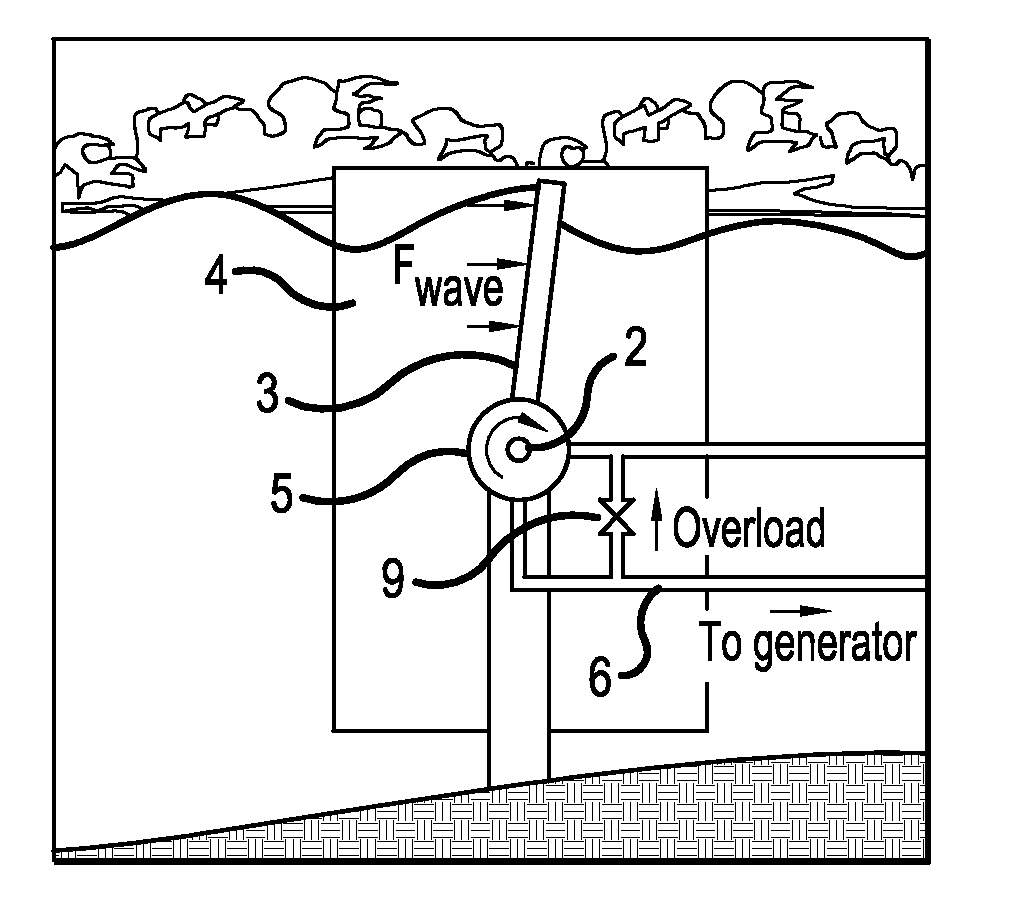
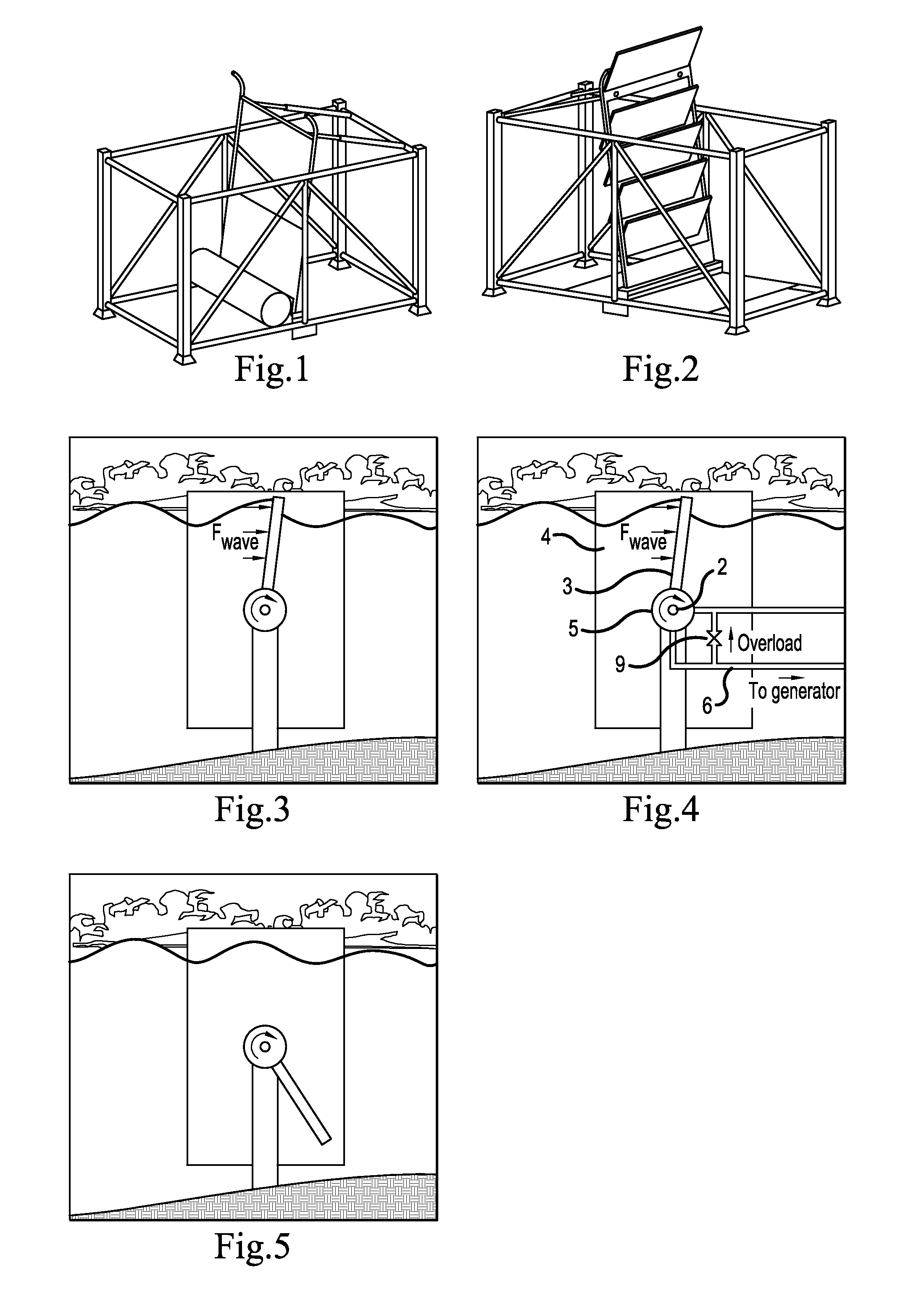
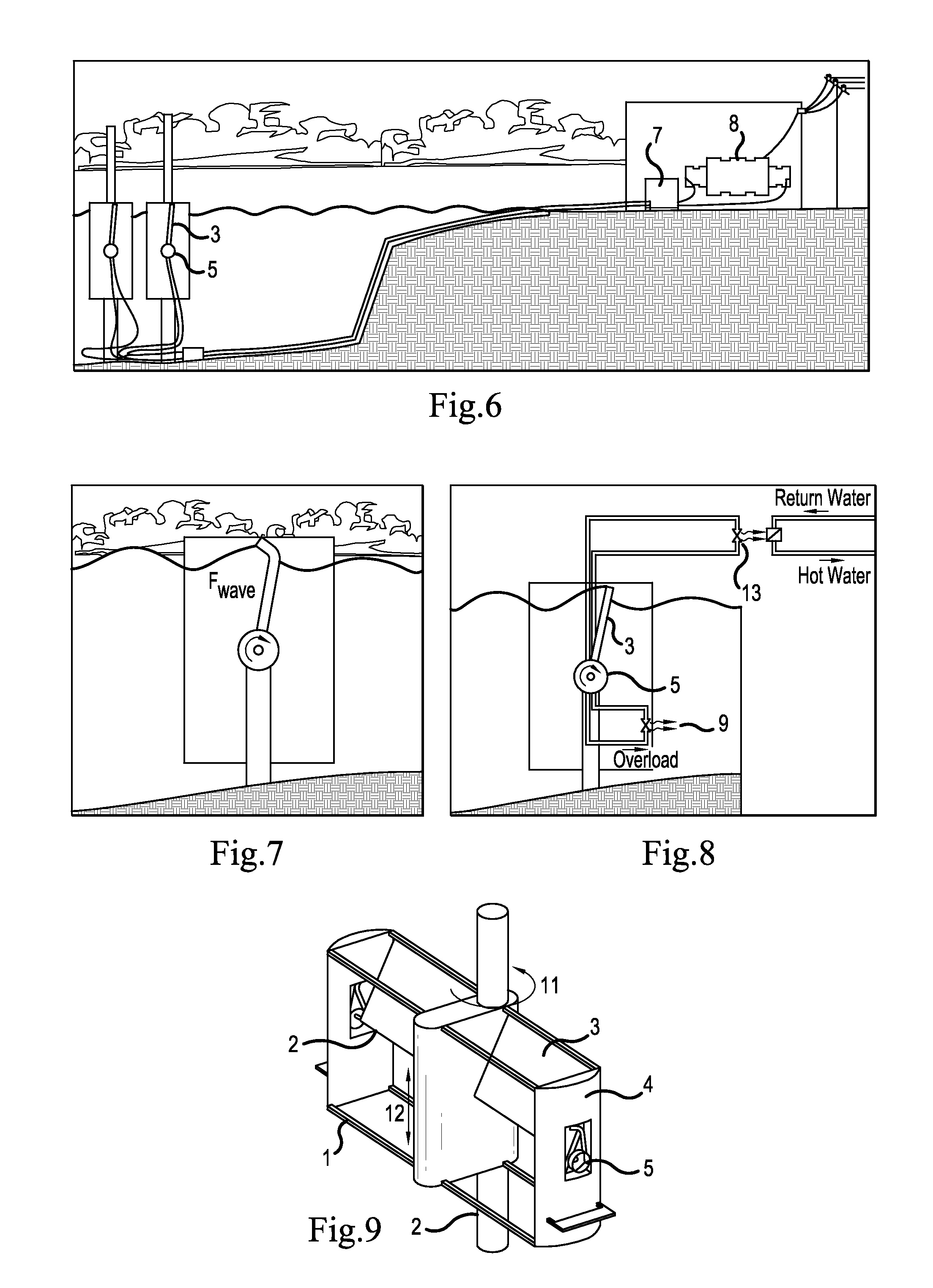
[0038]As shown in the figures, the wave energy converting apparatus according to the present invention comprises a frame 1 which supports a hinged 2 tilting or rotating barrier 3 in the form of a panel or a sail that tilts or rotates about the hinge 2 when a wave and associated wave pressure front pass the barrier in the form of a panel / sail 3. It is preferred that the axis of the barrier in the form of a panel / sail 3 and the frame supporting the same are positioned so that said axis 2 is essentially perpendicular to the passing wave pressure fronts, thereby obtaining a maximum energy collecting effect of the barrier in the form of a panel / sail 3.

[0039]The barrier in the form of a panel / sail 3 may be configured in different ways. In its simplest form, the bather 3 is in the form of a panel that tilts about the hinge 2. Alternatively, as shown in FIG. 1, the barrier 3 may comprise a square frame containing a sail of flexible cloth of an essentially impermeable material. Such a cloth ...


PUM


Abstract

An improved wave energy collecting apparatus comprising a frame (1) including at least one hinged (2) vertically tilting or rotating surface (3), such as a barrier in the form of a panel or a sail, for collecting energy from passing wave pressure fronts via a tilting or rotating motion within the frame (1), wherein the hinge (2) is positioned below the surface of the fluid at the trough of the passing waves, said barrier (3) being connected to a device capable of transforming the tilting or rotating motion into different types of energy, wherein the apparatus is located at a depth such that the tilting or rotating barrier (3) breaks the surface of passing waves at the crest of the waves. Such an apparatus may also include vertically positioned side walls (4) for directing the pressure fronts from passing waves towards the tilting barrier (3).

Description

BACKGROUND OF THE INVENTION[0001](1) Field of the Invention[0002]The present application relates to an apparatus for collection and conversion of wave energy in a fluid mass, said apparatus comprising a frame including a hinged vertically tilting surface, such as a barrier in the form of a panel or a sail, for collecting energy from passing wave pressure fronts and liquid particle motion via a tilting or rotating motion within the frame, wherein the hinge is positioned below the surface of the fluid at the trough of the respective waves, said barrier in the form of a panel or a sail being connected to a device capable of converting the tilting motion or rotational motion into different types of energy. According to an example of embodiment, the apparatus will be positioned as perpendicular as possible to the direction of travel of the waves and will be placed at a depth such that the tilting or rotating barrier in the form of a panel or a sail barely breaks the surface of the fluid ...

Claims


Application Information

Patent Timeline
Patent Type & Authority Patents(United States)
IPC IPC(8): E02B9/00
CPCF03B13/182F03D9/008F05B2240/12F05B2240/911Y02E10/728F05B2260/406F05B2260/74Y02E10/28Y02E10/38F05B2240/97Y02E10/30F03B13/14F03B13/18F03B17/06Y02E10/20
Inventor ESPEDAL, JULIUS
Owner LANGLEE WAVE POWER
Why Eureka
Try Eureka