Guided control device for unmanned vehicle

a technology for unmanned vehicles and control devices, which is applied in the direction of process and machine control, distance measurement, instruments, etc., can solve the problems of control error, guidance error p, and other errors, so as to improve work efficiency, reduce the target speed v of the unmanned vehicle, and improve the guiding speed

Active Publication Date: 2012-10-02
KOMATSU LTD
View PDF16 Cites 13 Cited by
  • Summary
  • Abstract
  • Description
  • Claims
  • Application Information

AI Technical Summary

Benefits of technology

[0013]The present invention has been contrived in view of such circumstances, and it is an object of the present invention to increase the guiding speed while preventing the unmanned vehicle from straying from the travel passage width, to improve the work efficiency.
[0015]Therefore, in a location where the travel passage width 80 is narrow, low target speed V1 is set and the unmanned vehicle 10 is caused to travel at the low guiding speed, thus the unmanned vehicle 10 is prevented from straying from the travel passage width 80 as in the conventional art. In a location where the travel passage width 80 is wide, high target speed V2 is set and the unmanned vehicle 10 travels at the high guiding speed. Even if the guiding speed increases in the location where the travel passage width 80 is wide, and the guidance error increases accordingly, the unmanned vehicle 10 does not stray from the travel passage width 80 because of the wide travel passage width 80. The wider the travel passage width 80, the higher the guiding speed at which the unmanned vehicle 10 can travel, whereby the work efficiency is improved as compared with the conventional art.
[0017]Therefore, as with the first invention, the wider the travel passage width 80, the higher the higher the guiding speed at which the unmanned vehicle 10 can travel. Therefore, the work efficiency is improved as compared with the conventional art. Moreover, the wider the travel passage width 80 is, the wider the guidable width 90. Therefore, the width at which the unmanned vehicle 10 is subjected to guided travel control can be increased.
[0019]In this manner, the wider the travel passage width 80 (guidable width 90) becomes, the higher the target speed V is set, and the unmanned vehicle 10 is caused travel at higher guiding speed, thus the work efficiency is improved. Moreover, the more the unmanned vehicle 10 strays from the target travel course 70 to approach the borderline 91 of the guidable width 90, the lower the target speed V becomes, whereby the vehicle 10 is caused to travel at lower guiding speed, thus the vehicle 10 can be prevented from straying from the guidable width 90 and from approaching the borderline 81 of the travel passage width 80.
[0020]According to a fourth aspect of the invention, as shown in FIG. 4, the unmanned vehicle 10 travels along a travel path 60 having adjacent inbound / outbound traffic lanes 61, 62 while being in a opposite direction to a direction of a vehicle on an oncoming lane. When it is determined that a vehicle 10′ traveling along the oncoming lane 62 approaches the unmanned vehicle 10, the target speed V of the unmanned vehicle 10 is reduced, whereby the unmanned vehicle 10 is caused to travel at low guiding speed. As a result, the occurrence of a risk of interference with the oncoming vehicle 10′ can be prevented, and the unmanned vehicle 10 can be guided more safely.

Problems solved by technology

When the unmanned vehicle 10 is subjected to guided travel control, a control error occurs, or another error occurs due to skid of the wheels.
For this reason, it is inevitable that the guidance error ΔP occurs.

Method used


Image

  • Guided control device for unmanned vehicle
  • Guided control device for unmanned vehicle
  • Guided control device for unmanned vehicle

Examples


first embodiment

The Guidable Width 90 is Created by the Control Station 20

[0079]The present embodiment assumes a case in which the guidable width 90 is created by the control station 20.

[0080]FIG. 6 is a flowchart showing a processing procedure performed in the first embodiment.

[0081]FIG. 6A shows processing performed by the unmanned vehicle 10, while FIG. 6B shows processing performed by the control station 20.

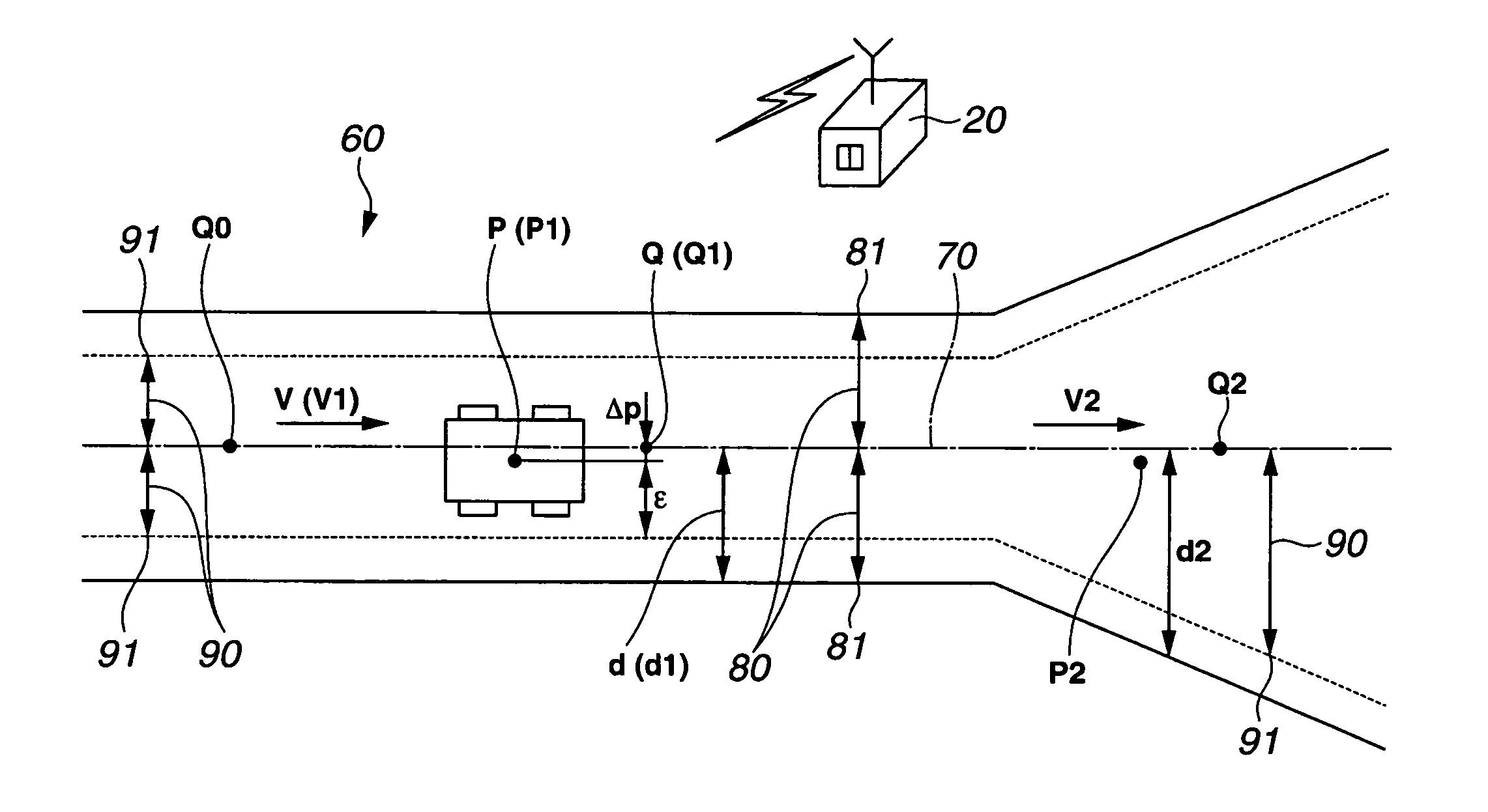
[0082]The control station 20 reads the current position P of the unmanned vehicle 10, the target travel course 70, and the terrain data (survey line information) on the travel path 60 (step 106).

[0083]Next, the guidable width 90 is set based on the current position P of the unmanned vehicle 10, the target travel course 70, and the terrain data (survey line information) on the travel path 60.

[0084]The control station 20 determines, based on the data on the current position P sent from the unmanned vehicle 10, which one of the target points Q on the target travel course 70 the unmanned vehicle...

second embodiment

The Guidable Width 90 is Created by the Unmanned Vehicle 10

[0113]The present embodiment assumes a case in which the guidable width 90 is created by the unmanned vehicle 10.

[0114]FIG. 8 is a flowchart showing a processing procedure performed in the second embodiment.

[0115]The unmanned vehicle 10 reads the current position P of the unmanned vehicle 10, the target travel course 70, and the terrain data (survey line information) on the travel path 60 (step 201).

[0116]Next, the guidable width 90 is created based on the current position P of the unmanned vehicle 10, the target travel course 70, and the terrain data (survey line information) on the travel path 60.

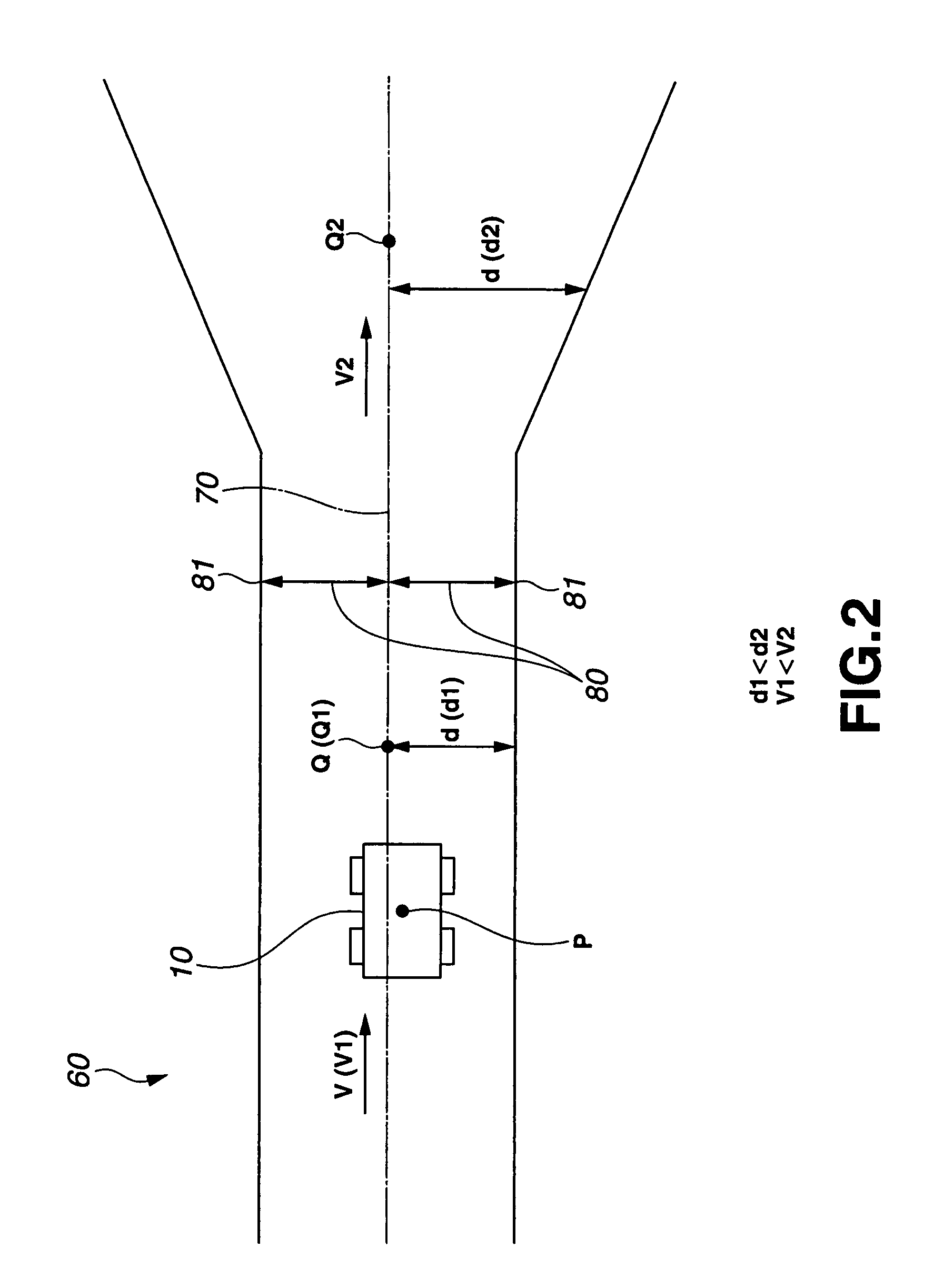
[0117]The unmanned vehicle 10 determines, based on the data on the current position P on this vehicle 10, which one of the target points Q on the target travel course 70 the unmanned vehicle 10 travels at. As shown in FIG. 3A, the larger the distance d between the current point Q on the target travel course 70 and the travelable b...


PUM


Abstract

Guiding speed is increased while an unmanned vehicle is prevented from straying from a travel passage width, to improve the work efficiency. Target speed of the unmanned vehicle increases as a distance between a current position of the unmanned vehicle and a guidable borderline increases, and the target speed of the unmanned vehicle decreases as the distance between the current position of the unmanned vehicle and a guidable borderline decreases. The unmanned vehicle travels, along a travel path having adjacent inbound / outbound lanes, in a direction opposite to a direction of a vehicle on an oncoming lane. If it is determined that the vehicle traveling along the oncoming lane is approaching the unmanned vehicle, then the target speed of the unmanned vehicle is reduced, whereby the unmanned vehicle is caused to travel at a low guiding speed.

Description

CROSS-REFERENCE TO RELATED APPLICATION[0001]This application claims priority of Japanese Patent Application 2006-218232 filed on Aug. 10, 2006.BACKGROUND OF THE INVENTION[0002]1. Technical Field[0003]The present invention relates to a guided travel control device for an unmanned vehicle, and more particularly to a device for guiding and moving an unmanned vehicle along a target travel course at a target speed without generating a guidance error between the target travel course and the current position of the unmanned vehicle.[0004]2. Related Art[0005]In a wide working site, such as a rock-crushing site or mine, sediment transport is carried out by driving an unmanned vehicle such as an unmanned dump truck. As shown in FIG. 1, an unmanned vehicle 10 is guided and moved along a target travel course 70 at target speed V by feeding back a guidance error ΔP between a target position Q on the target travel course 70 and the current position P of the unmanned vehicle 10 so that this guidan...

Claims


Application Information

Patent Timeline
Patent Type & Authority Patents(United States)
IPC IPC(8): G01C22/00G05D1/00
CPCG05D1/0278G05D1/027G05D1/0272
Inventor SUDOU, TSUGIONISHIJIMA, AKIHARU
Owner KOMATSU LTD
Why Eureka
Try Eureka