
Control apparatus for internal combustion engine

a control apparatus and internal combustion engine technology, applied in the direction of electrical control, process and machine control, instruments, etc., can solve the problems of fluctuation inability to maintain or improve the accuracy of fuel injection quantity, and inability to maintain the validity of the validity period

Active Publication Date: 2012-10-02
HITACHI ASTEMO LTD
View PDF17 Cites 8 Cited by
  • Summary
  • Abstract
  • Description
  • Claims
  • Application Information

AI Technical Summary

Benefits of technology

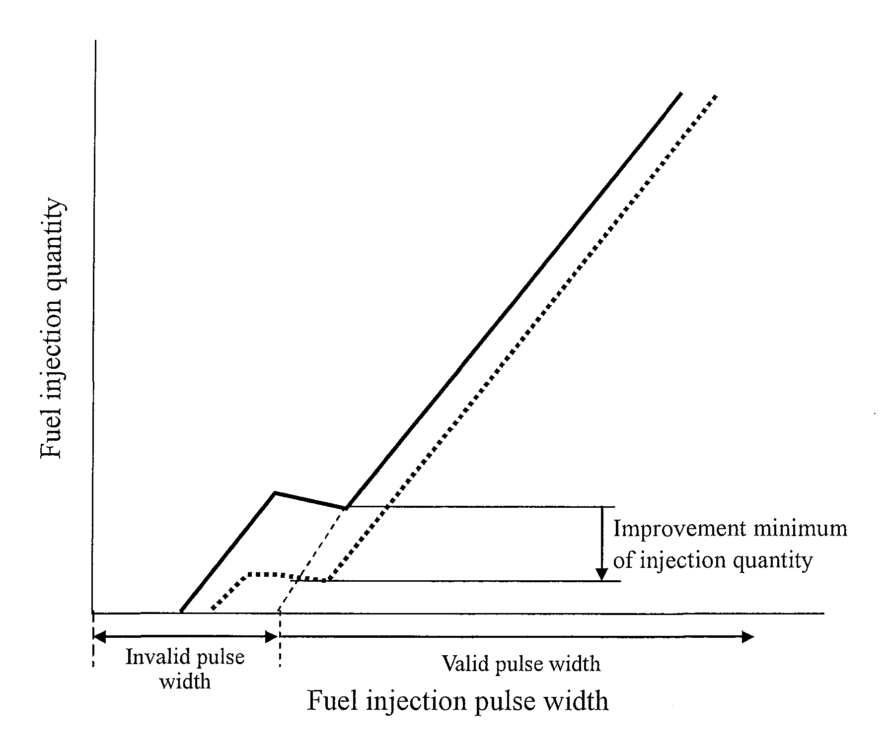
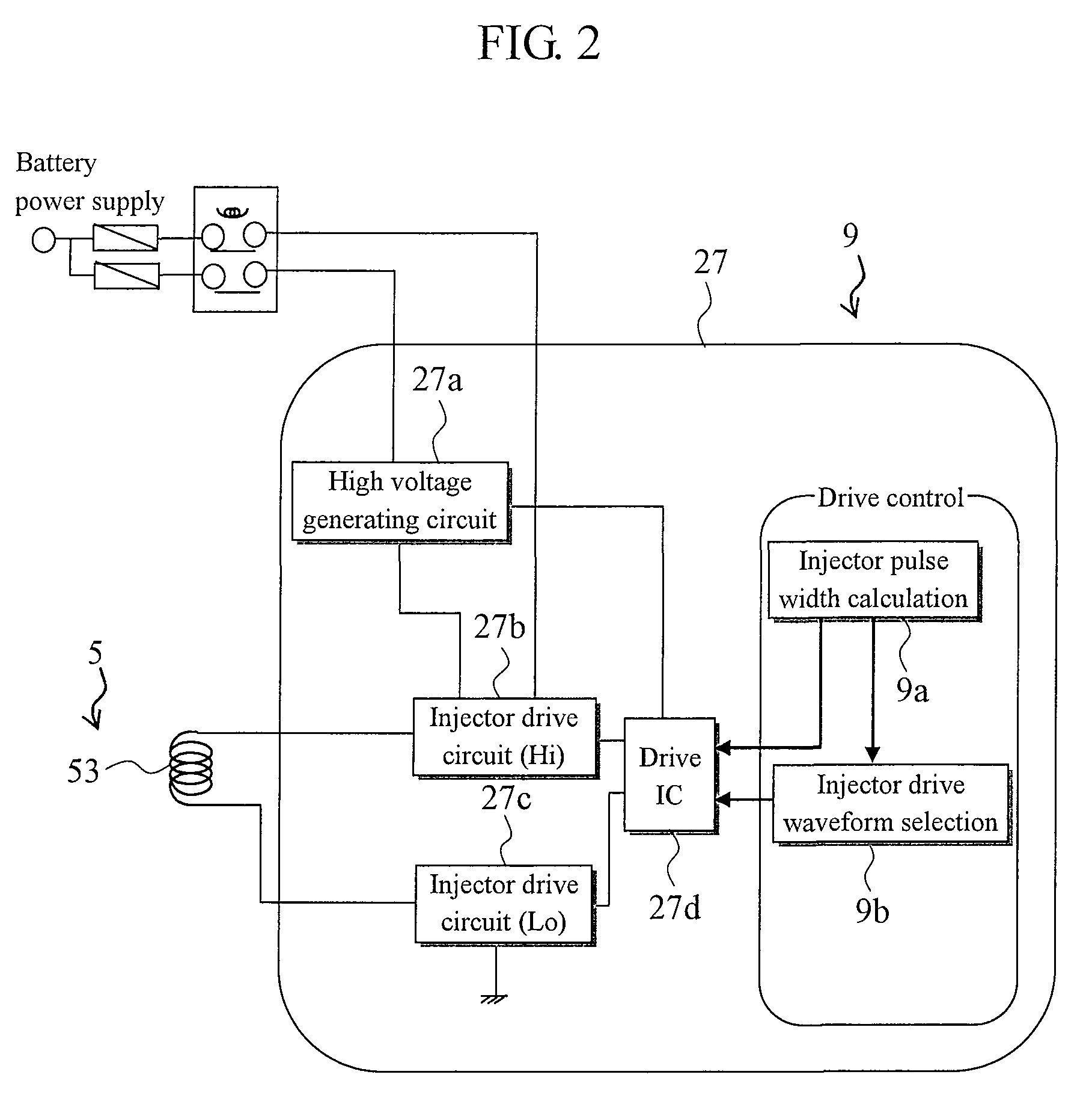
The present invention provides a fuel injection control apparatus for an internal combustion engine that can accurately inject a small amount of fuel even when the fuel injection quantity is reduced compared to the past. The apparatus includes a fuel injector, a fuel pressure sensor, and operation state detecting means. The apparatus calculates a valid pulse width and an invalid pulse width based on the fuel pressure and the valve opening delay. The fuel injector control means calculates a fuel injection pulse width based on the valid pulse width and the invalid pulse width, and controls the fuel injector accordingly. This ensures that the accuracy of the fuel injection quantity is maintained or improved even when the current waveform or the current value of the drive current is changed.

Problems solved by technology

Thus, an error in this invalid duration will have a direct major impact on accuracy of an injection quantity.
However, even if control of fuel injection is performed with the apparatuses of Patent Documents 1 to 4, fluctuation of fuel injection quantity occurred sometimes due to a response delay.

Method used


Image

  • Control apparatus for internal combustion engine
  • Control apparatus for internal combustion engine
  • Control apparatus for internal combustion engine

Examples


Embodiment Construction

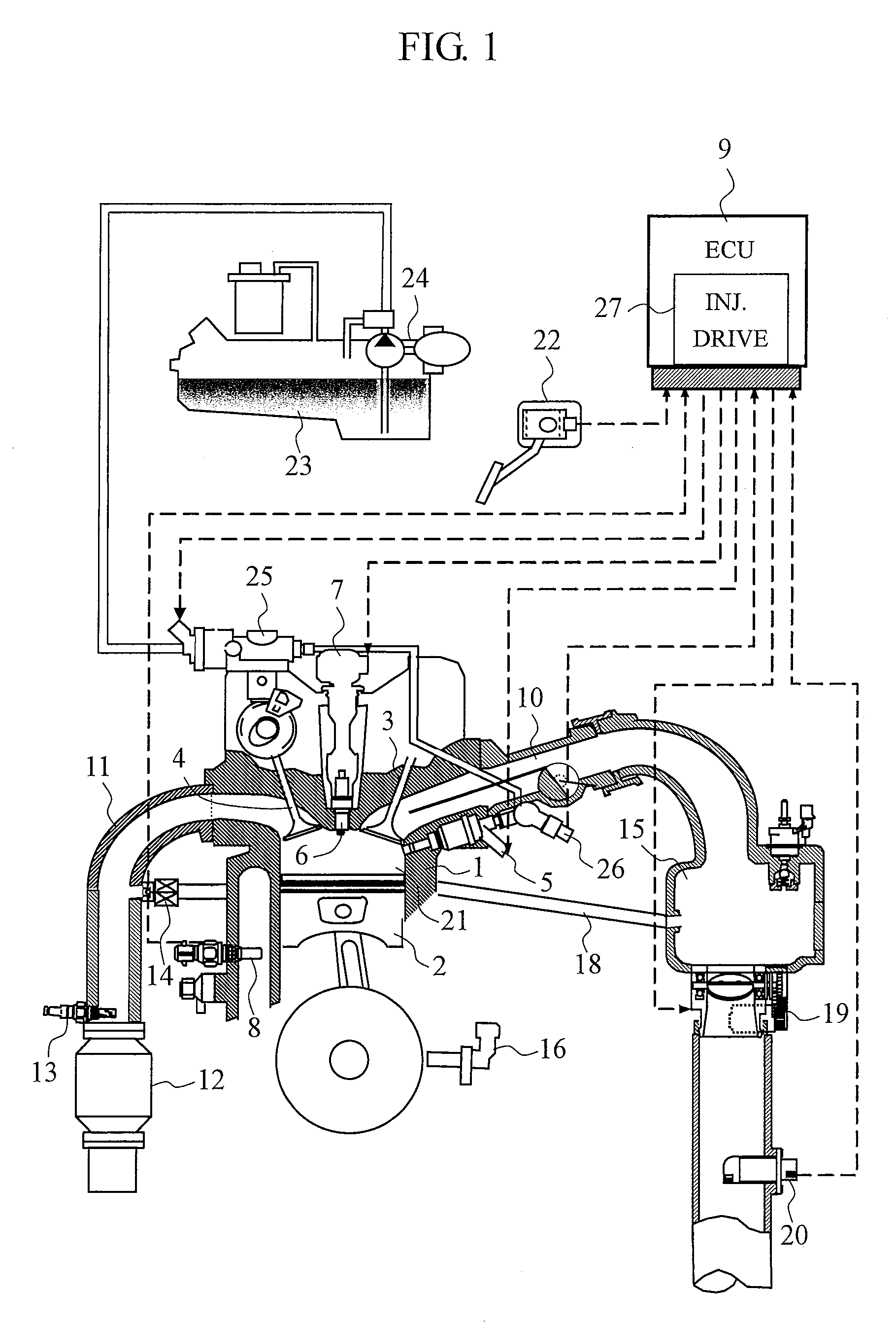
[0031]Hereinafter, with use of FIGS. 1 to 13, a configuration and an operation of a fuel injection control apparatus for injecting a fuel directly into a combustion chamber of an internal combustion engine according to the present embodiment of the present invention will be described.

[0032]Firstly, a configuration of an internal combustion engine system to which a fuel injection control apparatus according to the present embodiment is mounted will be described. FIG. 1 is an overall configuration diagram of the internal combustion engine system to which the fuel injection control apparatus according to the present embodiment is mounted.

[0033]An internal combustion engine (engine) 1 has a piston 2, an intake valve 3, and an exhaust valve 4. Intake air to the internal combustion engine 1 (incoming air) passes through an air flowmeter (AFM) 20, has a flow rate regulated by a throttle valve 19, and is supplied to a combustion chamber 21 of the engine 1 through an intake pipe 10 and the i...


PUM


Abstract

A fuel injection control apparatus for an internal combustion engine which can inject a fuel injection quantity to a fuel injector with accuracy even when the fuel injection quantity is reduced than before is provided. A fuel injection control apparatus of a direct cylinder injection type of internal combustion engine, including a fuel injector which performs fuel injection by supplying a drive current to a solenoid, a fuel pressure sensor which detects fuel pressure supplied to the fuel injector, and operation state detecting means which detects the operation state of the internal combustion engine, comprises current profile changing means 100 which has multiple current profiles of the drive current and changes current profiles based on the operation state and the fuel pressure, valid pulse width calculating means 701 which calculates a valid pulse width for opening and driving the fuel injector, invalid pulse width calculating means 103 which calculates an invalid pulse width, and fuel injector control means which calculates a fuel injection pulse width based on the valid pulse width and the invalid pulse width, and controls the fuel injector based on the fuel injection pulse width, wherein the invalid pulse width calculating means 103 calculates an invalid pulse width corresponding to the current profiles to be changed before the current profiles are changed.

Description

BACKGROUND OF THE INVENTION[0001]1. Field of the Invention[0002]The present invention relates to a fuel injection control apparatus for an internal combustion engine, and particularly to a fuel injection control apparatus preferred for fuel injection of a direct cylinder injection type of an internal combustion engine.[0003]2. Background Art[0004]An internal combustion engine is provided with a fuel injection control apparatus which controls an injector. The fuel injection control apparatus calculates an appropriate fuel injection quantity in accordance with an operation state of the internal combustion engine and drives and controls an injector which supplies fuel. An injector is of an electromagnetic type which supplies a current through an electromagnetic coil (solenoid) contained in the injector in order to open the injector and keep a valve opening state. This generates an electromagnetic force by which opening / closing operation of a plunger which constitutes an injector is per...

Claims


Application Information

Patent Timeline
Patent Type & Authority Patents(United States)
IPC IPC(8): F02M51/00
CPCF02D41/20F02D41/40F02D2041/2003F02D2041/2017F02D2200/0602Y02T10/44Y02T10/40
Inventor TOYOHARA, MASAHIROOKAMOTO, TAKASHIOHISA, TOMOHIROISHII, YOSHIKAZU
Owner HITACHI ASTEMO LTD
Learn More