Slip formed concrete wind turbine tower

a wind turbine and concrete technology, applied in the direction of building components, structural elements, domestic objects, etc., can solve the problems of limiting limiting the height of the turbine, and difficulty in cost effective erecting towers of optimal heights in many locations, so as to improve the efficiency of the turbine, and reduce the cost

Inactive Publication Date: 2012-10-09
FWS TECH HLDG
View PDF29 Cites 20 Cited by
  • Summary
  • Abstract
  • Description
  • Claims
  • Application Information

AI Technical Summary

Benefits of technology

[0020]By providing a slip form for forming the concrete tower, the tower can be manufactured in an efficient manner while further permitting a suitable lifting device to be carried to the top of the tower on the slip form as the tower is formed. The height of the tower is therefore not limited by the availability of suitable cranes so that a greater height of tower can be erected as the lifting device carried on the slip form can be used to lift the rotor, generator and nacelle into place instead of using a crane. Accordingly winds at greater elevation can be taken advantage of to improve the efficiency of the turbine. Furthermore the slip form technique for forming the tower permits the tower to be manufactured of relatively low cost components in a simple uniform structure of considerable strength.

Problems solved by technology

It is generally known that it is desirable to erect the tower as tall as possible to take advantage to high wind speeds however it is difficult to cost effectively erect towers of optimal heights in many locations, in part due to the limited availability of suitable cranes commonly used for lifting the rotor and nacelle onto the tower.
The availability of suitable cranes thus limits the height of the turbine which in turn limits the efficiency of the turbine.
Also due to the practical limitation of steel tube towers the height of the tower is also limited.
As described however cranes are still required for lifting the various components into position such that the overall height of the tower is still limited.
Furthermore the modular construction requires a considerable number of parts to be shipped to the construction site while also requiring specialised labour to assemble the complex structure thereof.

Method used


Image

  • Slip formed concrete wind turbine tower
  • Slip formed concrete wind turbine tower
  • Slip formed concrete wind turbine tower

Examples


Embodiment Construction

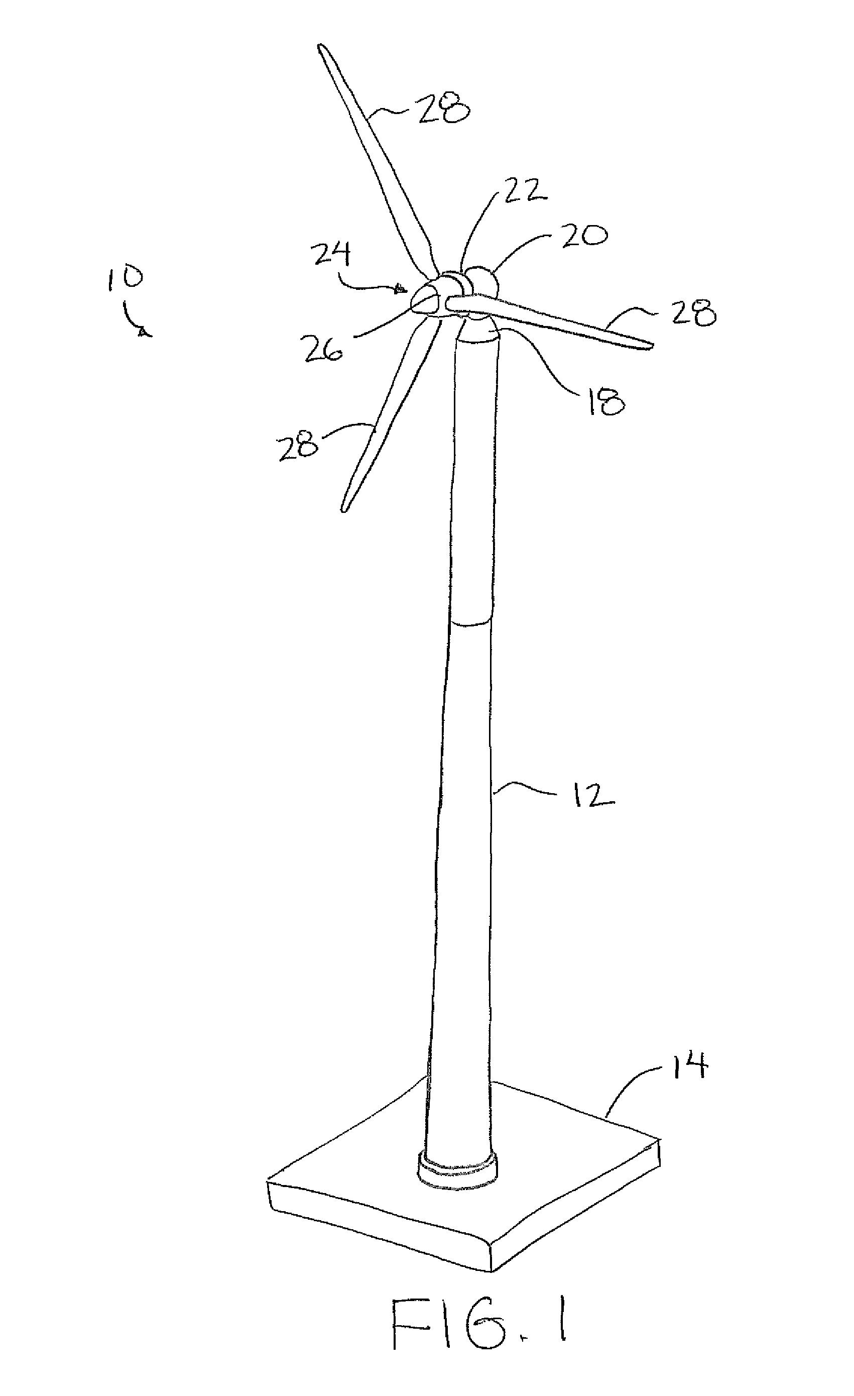
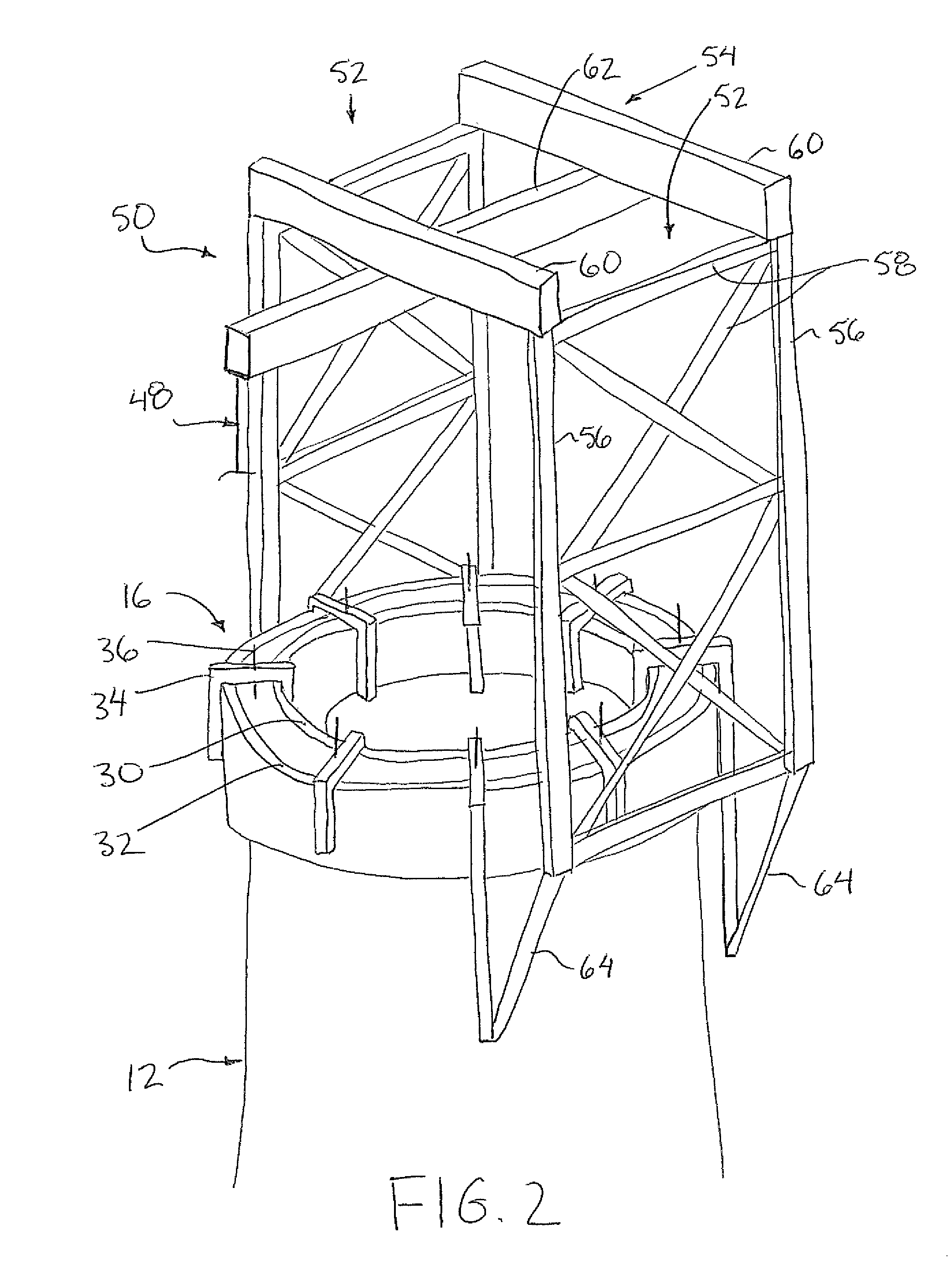
[0051]Referring to the accompanying figures there is illustrated a wind turbine generally indicated by reference numeral 10. The turbine 10 comprises a tower 12 supported on a suitable foundation 14 on the ground. The foundation comprises any suitable base in the form of a pad or piles in the ground and the like. The tower 12 is erected to extend upwardly from the foundation to a top end of the tower by using a slip form 16 as described and illustrated herein. The resulting tower is generally circular in cross section and is tubular in shape defining a hollow interior surrounded by a perimeter wall having an inner surface and an outer surface which are generally cylindrical in shape.

[0052]A transition member 18 is supported on the top end of the tower and serves to support a nacelle 20 thereon such that the nacelle is pivotal about a vertical pivot axis relative to the tower. A generator 22 and rotor 24 are supported on the nacelle for rotation about a horizontal turbine axis. The r...


PUM

PropertyMeasurementUnit
diameteraaaaaaaaaa
speedsaaaaaaaaaa
heightaaaaaaaaaa

Abstract

A wind turbine is formed of a concrete tower which is erected by slip forming. A primary lifting device is erected onto the tower by being lifted together with the slip form and being subsequently transferred onto the tower from the slip form after the tower has been formed. The nacelle, generator, and rotor of the turbine are then lifted onto the tower using the primary lifting device. A secondary lifting device supported on the tower is used to lower the primary lifting device to the ground after the nacelle, generator and rotor are assembled. The height of the tower is therefore not limited by the availability of suitable cranes so that a greater height of tower can be erected to take advantage of winds at greater elevation.

Description

[0001]This application claims the benefit under 35 U.S.C. 119(e) of U.S. provisional application Ser. No. 61 / 175,662, filed May 5, 2009.FIELD OF THE INVENTION[0002]The present invention relates a wind turbine comprising a concrete tower supporting a nacelle, generator and rotor thereon, and more particular the present invention relates to a method of erecting the wind turbine by forming the concrete tower using a slip form which also supports a gantry crane thereon for lifting the nacelle, the generator and the rotor onto the concrete tower.BACKGROUND[0003]Wind turbines typically comprise a tall tower supporting a nacelle, a generator and a rotor comprising a central hub and radially extending blades thereon. It is generally known that it is desirable to erect the tower as tall as possible to take advantage to high wind speeds however it is difficult to cost effectively erect towers of optimal heights in many locations, in part due to the limited availability of suitable cranes comm...

Claims


Application Information

Patent Timeline
Patent Type & Authority Patents(United States)
IPC IPC(8): E04H12/34F03D11/04
CPCE04G11/22F03D1/001F03D11/04E04H12/341F05B2240/916Y10T29/49631Y02E10/728Y10T29/49316Y02E10/726F03D13/20F03D13/10Y02E10/72
Inventor THOMPSON, BRADLEY D.
Owner FWS TECH HLDG
Why Eureka
Try Eureka