
Magnetic drive for food processing apparatus

a technology of magnetic drive and food processing equipment, which is applied in the direction of mixing, kitchen equipment, mixers, etc., can solve the problems of reducing the service life of the seal,

Active Publication Date: 2012-10-09
ISLAND OASIS FROZEN COCKTAIL
View PDF25 Cites 50 Cited by
  • Summary
  • Abstract
  • Description
  • Claims
  • Application Information

AI Technical Summary

Benefits of technology

"The patent text describes a magnetic drive for food processing equipment that includes a driving member outside the food-contact chamber and a driven member inside the chamber. The driving member has permanent magnet poles and the driven member has magnetically soft material that is supported from a rotating shaft in opposed relationship to the permanent magnet poles. This results in a more efficient and effective magnetic drive for food processing equipment."

Problems solved by technology

This seal is subject to considerable wear and tear over time, as is the mechanical coupling.
Because seal failure can result in liquid leaking out of the cup, the seal and bearings in the base of the cup are typically built to ensure sealing at the expense of friction.
The friction produces wear, heat, and loss of power.
Moreover, the conventional blender produces much unwanted noise, and the mechanical interlocking coupling between the plates can make it awkward or difficult to remove the cup from, and return the cup to, the base.
The straight-forward approach of placing a conventional electric motor directly under the blender cup increases the overall height of the machine, and therefore considered undesirable in connection with mechanical linkages.
Such split AC motor arrangements are limited by the torque, speed control, eddy current loss, and emf interference problems of a.c motors, as accentuated by the physical separation of the stator windings and the rotor.
They often do not provide good speed control.
Further, the inclusion of the rotor of the motor within the container or cup often adds unwanted weight to the cup assembly and makes the cup difficult to handle due to gyroscopic effects if it is picked up while the rotor is still spinning.
If the permanent magnet rotor of a brushless DC motor were to be located in the base of a blender cup, the cup would not only become heavy and exhibit a severe gyroscopic effect, but it would also “stick” to steel or iron sinks and countertops, and would attract loose steel or iron objects such as some flatware, barware, or coins.

Method used


Image

  • Magnetic drive for food processing apparatus
  • Magnetic drive for food processing apparatus
  • Magnetic drive for food processing apparatus

Examples


Embodiment Construction

[0043]This invention is not limited in its application to the details of construction and the arrangement of components set forth in the following description or illustrated in the drawings. The invention is capable of other embodiments and of being practiced or of being carried out in various ways. Also, the phraseology and terminology used herein is for the purpose of description and should not be regarded as limiting. The use of “including,”“comprising,” or “having,”“containing,”“involving,” and variations thereof herein, is meant to encompass the items listed thereafter and equivalents thereof as well as additional items.

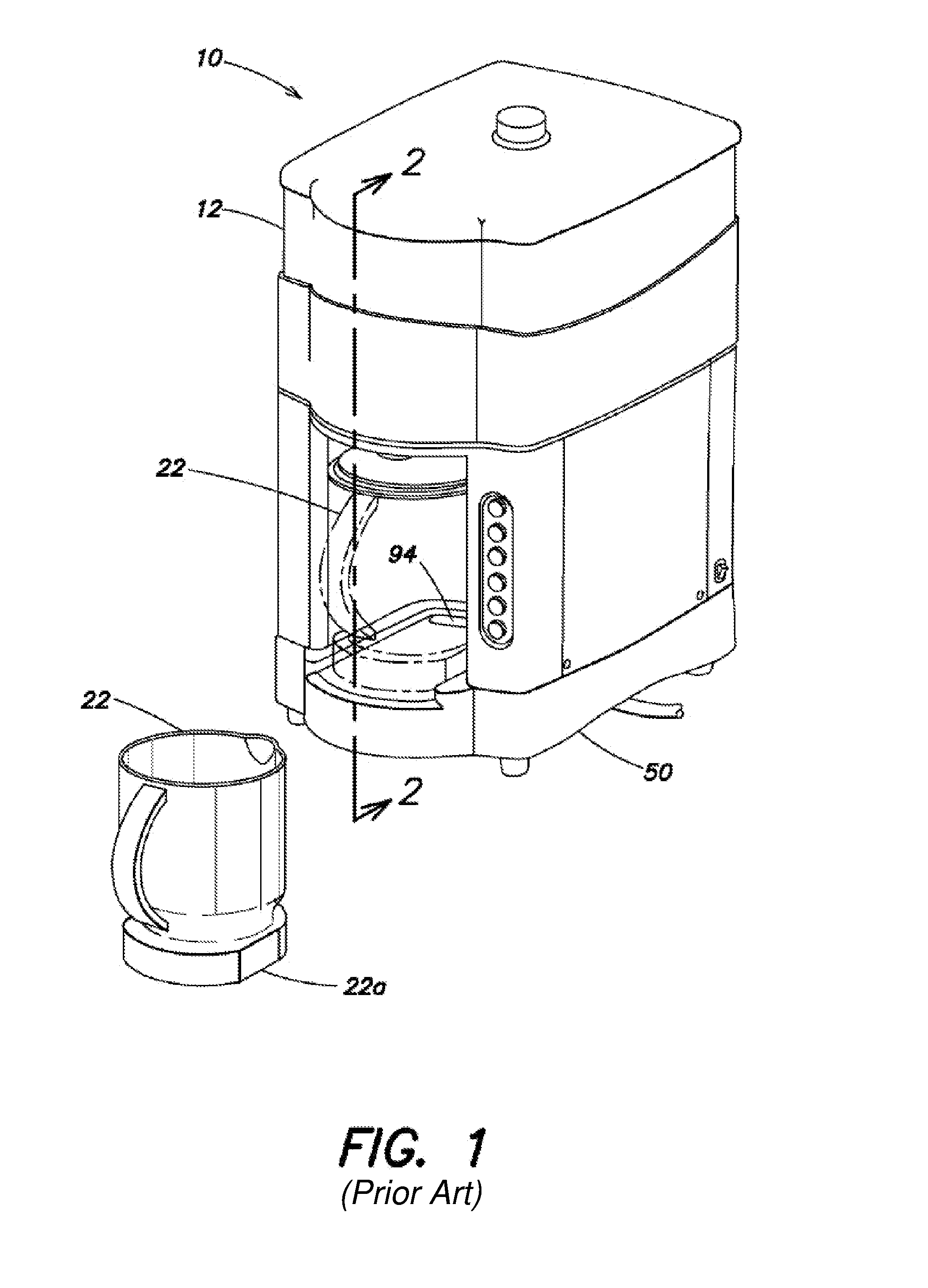
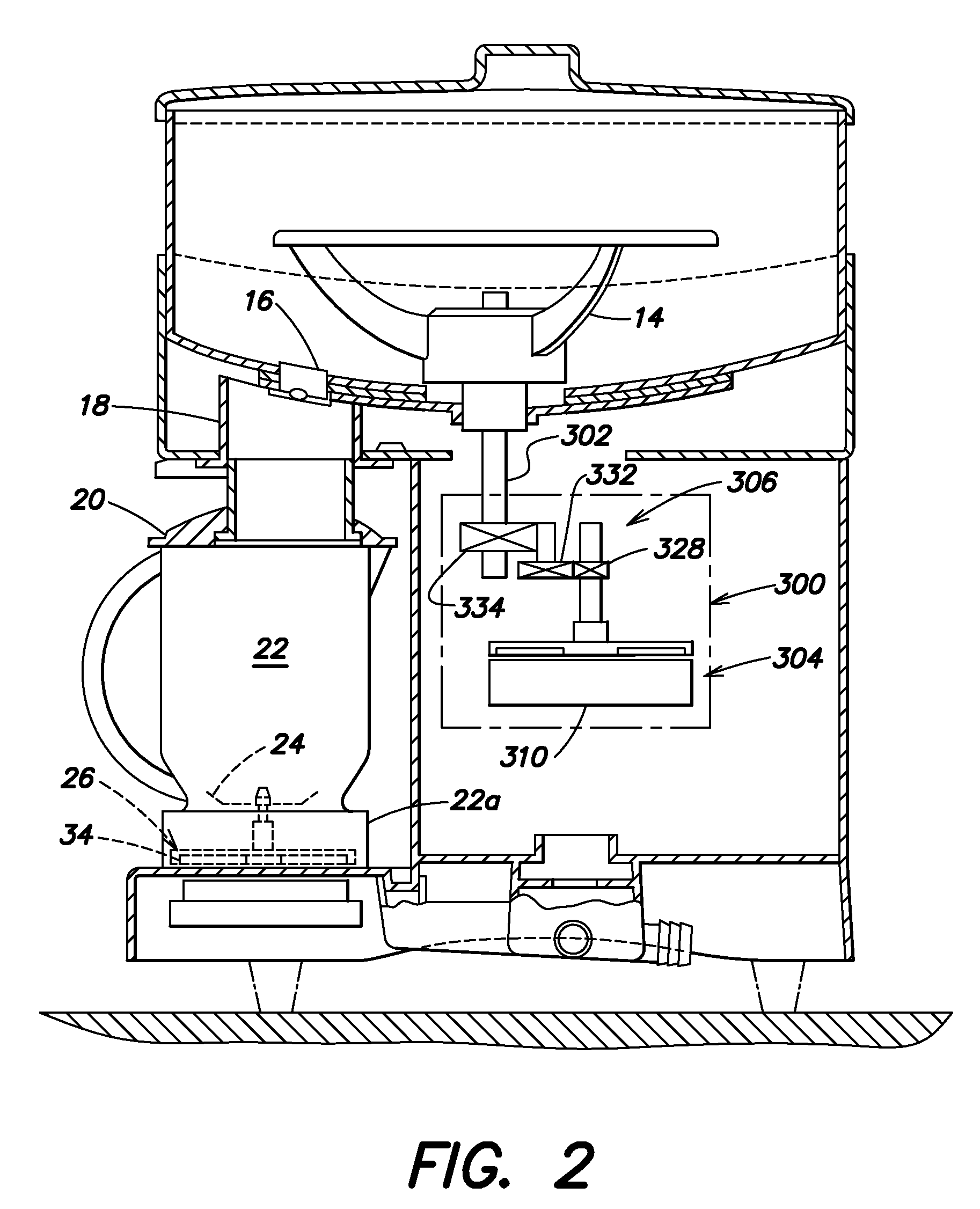
[0044]FIGS. 1 and 2 show a principal application of embodiments of aspects of the present invention, namely, in a blender / shaver machine 10 adapted to the automatic manufacture of frozen drinks in bars and restaurants. A supply of ice in a hopper 12 is fed by a rotating set of blades 14 to a blade 16. The shaved ice falls through a chute 18 including a lid 20 in...


PUM


Abstract

Food processing apparati including magnetic drives are described herein. According to one exemplary embodiment, a food processing apparatus may include a motor having a motor shaft, a rotor rotatably mounted on the motor shaft, and a stator producing an electromagnetic field for interacting with the rotor. The rotor may magnetically drive a drive plate coupled to an impeller inside a food-contact chamber.

Description

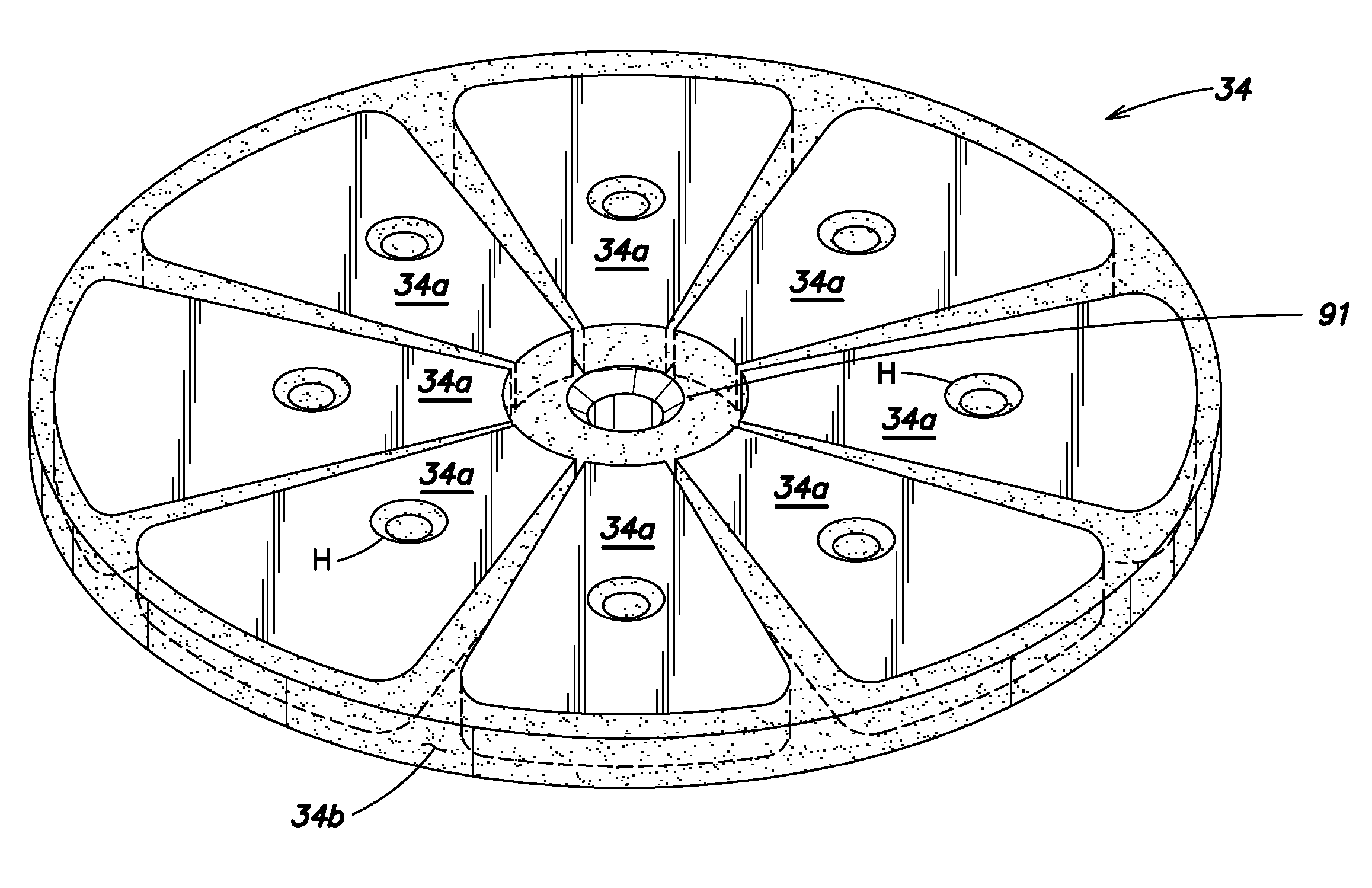
BACKGROUND OF INVENTION[0001]1. Field of Invention[0002]Embodiments described relate to magnetic drives for food processing equipment, particularly for food processing equipment including a food contact chamber separable from a motor drive unit, such as blenders, mixers and the like.[0003]2. Discussion of Related Art[0004]Conventional home blenders and mixers typically incorporate a mechanically-driven impeller rotatably mounted within a removable blender cup. The base of the cup incorporates a generally circular connection plate with a pattern of projections and / or depressions formed on its lower face that is removably mateable, using a vertical, drop-in movement, with a corresponding pattern formed on a like plate attached to the shaft of a motor housed in a base of the machine. This mechanical coupling between the blender cup and the blender motor often requires a rotary seal at the base of the cup between the impeller and connecting plate. This seal is subject to considerable we...

Claims


Application Information

Patent Timeline
Patent Type & Authority Patents(United States)
IPC IPC(8): B01F13/08
CPCA47J43/0465A47J43/085
Inventor KARKOS, JR., JOHN F.FLANARY, RON
Owner ISLAND OASIS FROZEN COCKTAIL
Learn More