
Transmission oil-pressure control apparatus and methods

a technology of automatic transmission and control apparatus, which is applied in mechanical apparatus, transportation and packaging, propulsion parts, etc., can solve the problems of high price inability to actively control the engagement rate reduction rate, and high cost of oil-pressure control valves. , to achieve the effect of reducing the control pressur

Inactive Publication Date: 2012-10-09
NISSAN MOTOR CO LTD
View PDF9 Cites 5 Cited by
  • Summary
  • Abstract
  • Description
  • Claims
  • Application Information

AI Technical Summary

Benefits of technology

This solution reduces costs by using a single common oil-pressure control valve, balances engagement pressure reduction and increase rates to minimize selection shock and enhance response, and prevents delays in engagement, thereby improving the overall shifting performance of the automatic transmission.

Problems solved by technology

Accordingly, the engagement-pressure reduction rate cannot be actively controlled.
In addition, in an R→N→D selection operation in which the range is switched to the D range immediately after the R→N selection operation or in a D→N→R selection operation in which the range is switched to the R range immediately after the selection operation, the following problems occur in addition to the above-described problems.
Therefore, the forward shifting friction element or the reverse shifting friction element is too quickly set to the engaged state and there is a risk that an engagement shock (selection shock) will occur.
Because oil-pressure control valves are expensive compared to directional control valves, high costs are incurred.
In addition, because the oil-pressure control valve starts a pressure adjusting operation after switching of the manual valve is detected, the above-described problems cannot be solved.
This increases the delay in the engagement response of the shifting friction elements, and a new problem occurs in that the shifting response is degraded.

Method used


Image

  • Transmission oil-pressure control apparatus and methods
  • Transmission oil-pressure control apparatus and methods
  • Transmission oil-pressure control apparatus and methods

Examples


Embodiment Construction

[0030]Embodiments of the present disclosure will be described in detail below with reference to the drawings.

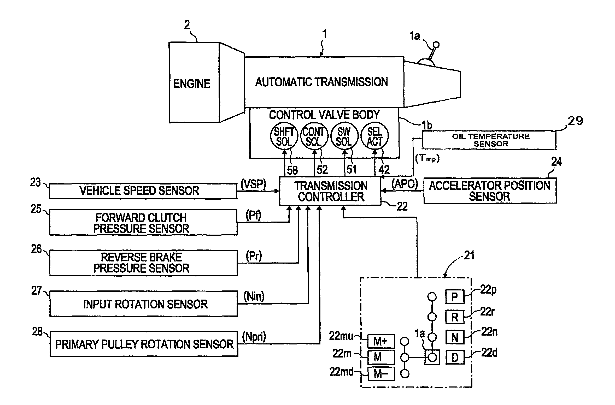
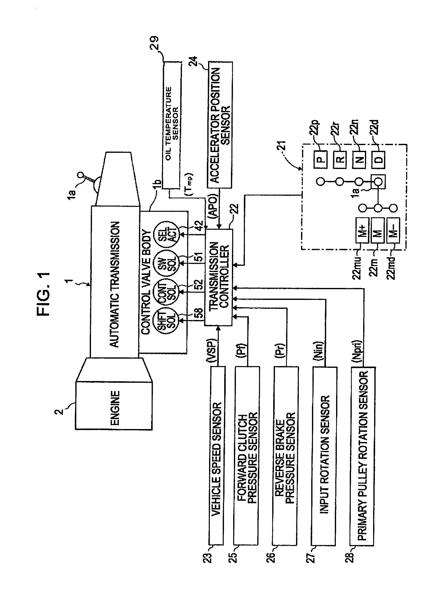
[0031]Referring to FIG. 1, a control system of an automatic transmission 1 having a shifting oil-pressure control apparatus according to embodiments of the present disclosure, is shown. The automatic transmission 1 has an engine 2 connected thereto at a left end thereof in the figure (at an input side), and outputs the rotation of the engine 2 after changing the rotational speed in accordance with the selected transmission gear ratio.

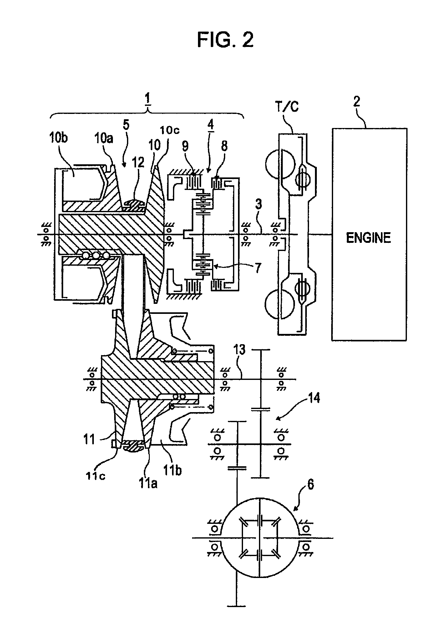
[0032]As shown, the automatic transmission 1 is a V-belt type continuously variable transmission (see FIG. 2), but it should be understood that any type of automatic transmission may be used with embodiments disclosed herein. Automatic transmisstion 1 may include an input shaft 3 to which the rotation of the engine 2 may be input through a lock-up torque converter T / C, a forward-reverse switching mechanism 4, a V-belt power transmission mechanism...


PUM


Abstract

A control apparatus of a vehicle transmission includes a hydraulic circuit configured to activate at least one friction element with a control pressure, a selector configured to select a range of the transmission, a valve configured to switch a transmission shifter, and a control unit configured to direct the valve to switch the transmission shifter in response to the selected transmission range and to reduce the control pressure prior to switching the transmission shifter. A method to control a vehicle transmission includes activating at least one friction element with a control pressure, selecting a desired range of the transmission, switching a transmission range in response to the selected desired transmission range, and reducing the control pressure prior to switching the transmission range.

Description

CROSS-REFERENCE TO RELATED APPLICATIONS[0001]The present application claims priority from Japanese Patent Application No. 2008-043813, filed Feb. 26, 2008. The contents of the priority application are hereby incorporated by reference in their entirety.BACKGROUND OF THE DISCLOSURE[0002]1. Field of the Disclosure[0003]The present disclosure is applicable to any type of automatic transmission (for example, a continuously variable transmission, a multi-range transmission, an automatic manual transmission, which is a manual transmission that involves the use of automatic gear shifts, etc.). More specifically, the present disclosure relates to a shifting oil-pressure control apparatus for an automatic transmission which may provide improved controllability and responsiveness of a shifting oil pressure when a selection operation for switching between a driving range and a non-driving range is performed by a driver.[0004]2. Description of the Related Art[0005]In an automatic transmission, a...

Claims


Application Information

Patent Timeline
Patent Type & Authority Patents(United States)
IPC IPC(8): B60W10/02B60W10/10
CPCF16H61/0021F16H61/061F16H61/662F16H2061/0485F16H2061/0488Y10T477/78F16H2306/44F16H2306/52F16H2312/09Y10T74/20024Y10T477/641F16H2061/6608
Inventor FUNAKOSHI, HIDEKAZUAKAZAWA, HIROAKIKIKUCHI, MASAHIKO
Owner NISSAN MOTOR CO LTD
Learn More