Brushless DC motor having multiple parallel windings

a dc motor and parallel winding technology, applied in the field of electric motors, can solve the problems of increasing the resistive power loss in the circuit providing energy, limiting the range or performance of the battery-powered electric motor, and reducing the resistive power loss in the supply circuit, so as to achieve the effect of low input voltag

Active Publication Date: 2012-10-09
FERRAN ROBERT J
View PDF28 Cites 36 Cited by
  • Summary
  • Abstract
  • Description
  • Claims
  • Application Information

AI Technical Summary

Benefits of technology

[0006]A brushless DC motor operates with lower input voltages. The motor is modular in design so that a plurality of stator sections are mechanically interconnected in tandem within a common housing with the stator sections providing magnetic fields to drive a rotor (armature) for the motor. Each stator section in the motor is wound with multiple sets of parallel windings on the poles of the stator section with each set of the windings interconnected to form a delta winding configuration or a wye (star) winding configuration. Each set of windings is connected to three terminals. Each of the three terminals of each of the set of windings in each stator section is coupled to a respective power input terminal so that each power input terminal of each set of windings is driven independently of the corresponding terminals on the other sets of windings of the stator section. Accordingly, the currents provided to each of the parallel sets of windings are reduced because of the cumulative effect of the parallel sets of windings on the same stator. The resistive losses in the circuitry to each set of windings and within each set of windings are reduced so that the voltages applied to each terminal of each set of windings are lower and can be maintained within a safe range for use on a watercraft.

Problems solved by technology

In general, vehicles driven by battery-powered electric motors have a limited range or limited performance (e.g., limited velocity and acceleration).
However, increasing the current provided to an electric motor increases the resistive power losses in the circuits providing energy to the motor.
Increasing the voltage to an electric motor decreases the resistive power losses in the supply circuits; however, high voltages are not desirable in vehicles and are particularly undesirable in a watercraft because of the unavoidable presence of water in proximity to the high voltages.

Method used


Image

  • Brushless DC motor having multiple parallel windings
  • Brushless DC motor having multiple parallel windings
  • Brushless DC motor having multiple parallel windings

Examples


Embodiment Construction

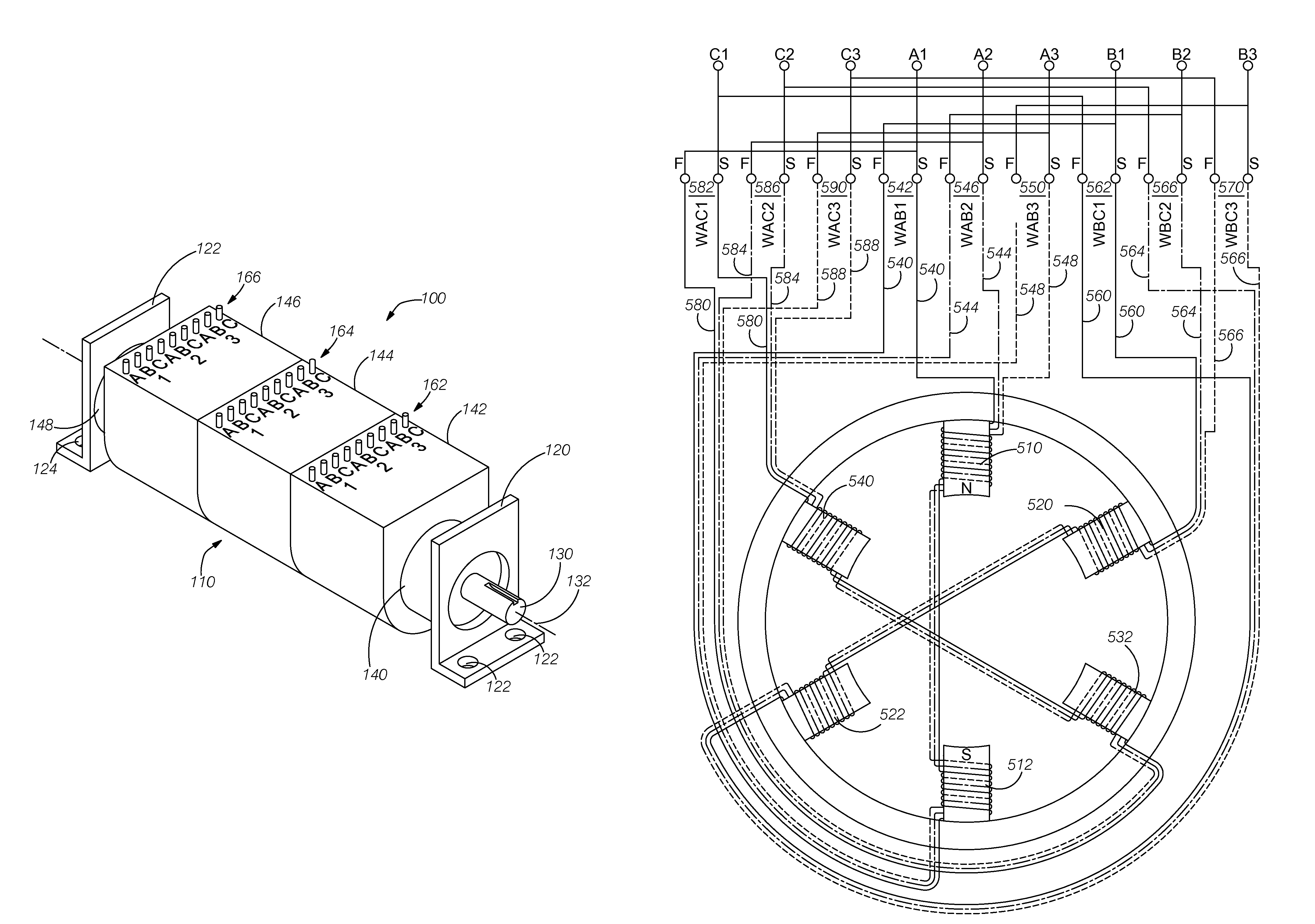
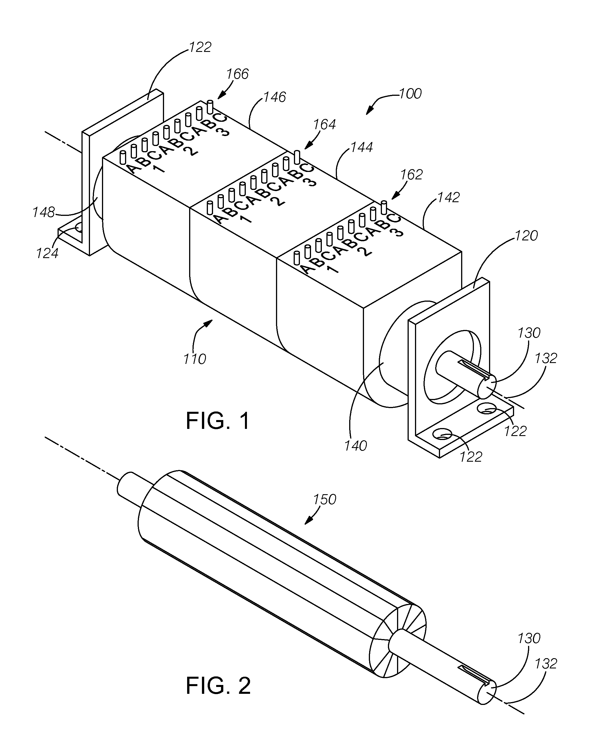
[0017]FIG. 1 illustrates a perspective view of an exemplary parallel winding electric motor 100 that embodies aspects of the present invention. The motor comprises an outer casing 110 having a mounting system to secure the motor to a watercraft or other vehicle. For example, in the illustrated embodiment, the motor includes a front L-shaped mounting bracket 120 and a rear L-shaped mounting bracket 122 proximate the respective ends of the casing. Each mounting bracket includes suitable mounting features (e.g., holes 124) to receive bolts to mount the motor. Other mounting systems can also be used to secure the motor to the watercraft or other vehicle. A rotatable shaft 130 passes through an opening in the mounting bracket at one end of the casing. The rotor rotates about a centerline 132. After mounting the motor in the watercraft, the shaft is coupled to a drive system (not shown), such as, for example, a propeller via suitable coupling devices.

[0018]In the illustrated embodiment, t...


PUM


Abstract

A brushless DC motor has at least three stator sections and a single rotor rotating with the three stator sections. Each stator section is wound with three parallel windings having respective three nodes. Each stator section has nine terminals providing independent access to each node so that separate voltages and currents are applied to each parallel winding in the stator section. Thus, the current applied to each stator section is divided substantially equally among the three parallel windings, thereby reducing the current in each winding for the same power requirement for the motor, which reduces the I2R losses in the windings and the supply wiring and reduces the power handling requirements in the electronic switches providing the supply voltages. The three parallel windings are connected to external terminals of the motor to form either a delta winding configuration or a wye (star) winding configuration.

Description

RELATED APPLICATIONS[0001]The present application claims the benefit of priority under 35 USC §119(e) to U.S. Provisional Application No. 61 / 380,694, filed on Sep. 7, 2010.BACKGROUND OF THE INVENTION[0002]1. Field of the Invention[0003]The present invention is generally in the field of electric motors that receive electrical energy from an energy storage device and that drive a propulsion system.[0004]2. Description of the Related Art[0005]Battery-powered electric motors are well known and have been used to provide rotational energy to drive propulsion systems for vehicles, including, for example, watercraft. In general, vehicles driven by battery-powered electric motors have a limited range or limited performance (e.g., limited velocity and acceleration). In order to provide enhanced performance, additional energy must be supplied to the electric motors in the watercraft or other vehicle. Increasing the power necessitates increasing the voltage or the current or both the voltage an...

Claims


Application Information

Patent Timeline
Patent Type & Authority Patents(United States)
IPC IPC(8): H02K16/04
CPCH02K3/28H02K16/04H02K21/16H02K37/14
Inventor KAMINSKY, ILYAFERRAN, ROBERT J.
Owner FERRAN ROBERT J
Why Eureka
Try Eureka