
Apparatus and methods for self-powered communication and sensor network

a technology of self-powered communication and sensor network, applied in the field of transmission of information along a tubular string, can solve the problems of limited or specialized use of alternative methods of telemetry, such as low frequency electromagnetic and acoustics, and the difficulty of maintaining and maintaining each pipe section, and the acoustic system suffers from attenuation and filtering effects

Active Publication Date: 2012-10-09
BAKER HUGHES INC
View PDF42 Cites 96 Cited by
  • Summary
  • Abstract
  • Description
  • Claims
  • Application Information

AI Technical Summary

Benefits of technology

The present invention is a system and method for measuring and communicating along a tubular string, such as a drill string or well casing. The system includes multiple autonomous telemetry stations that extract power from potential energy sources and communicate with each other using a preferred transmission path determined at each location. The system allows for the efficient and reliable transmission of information along the tubular string.

Problems solved by technology

Alternative methods of telemetry, such as low frequency electromagnetic and acoustics, have been investigated and found to be of limited or specialized use.
U.S. Pat. No. 4,095,865 to Denison, et al, describes sections of drill pipe, pre-wired with an electrical conductor, however each section of pipe is specially fabricated and difficult and expensive to maintain.
Acoustic systems suffer from attenuation and filtering effects caused by reflections at each drill joint connection.
To date, the only practical and commercial method of MWD telemetry is modulation of mud flow and pressure with it's relatively slow data rate.
Any malfunction in the line puts the power transmission and communication in jeopardy.

Method used


Image

  • Apparatus and methods for self-powered communication and sensor network
  • Apparatus and methods for self-powered communication and sensor network
  • Apparatus and methods for self-powered communication and sensor network

Examples


Embodiment Construction

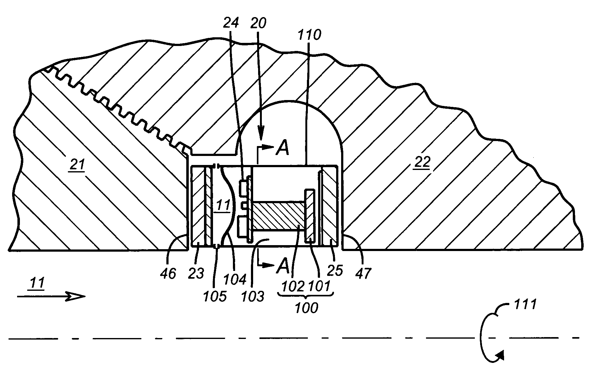
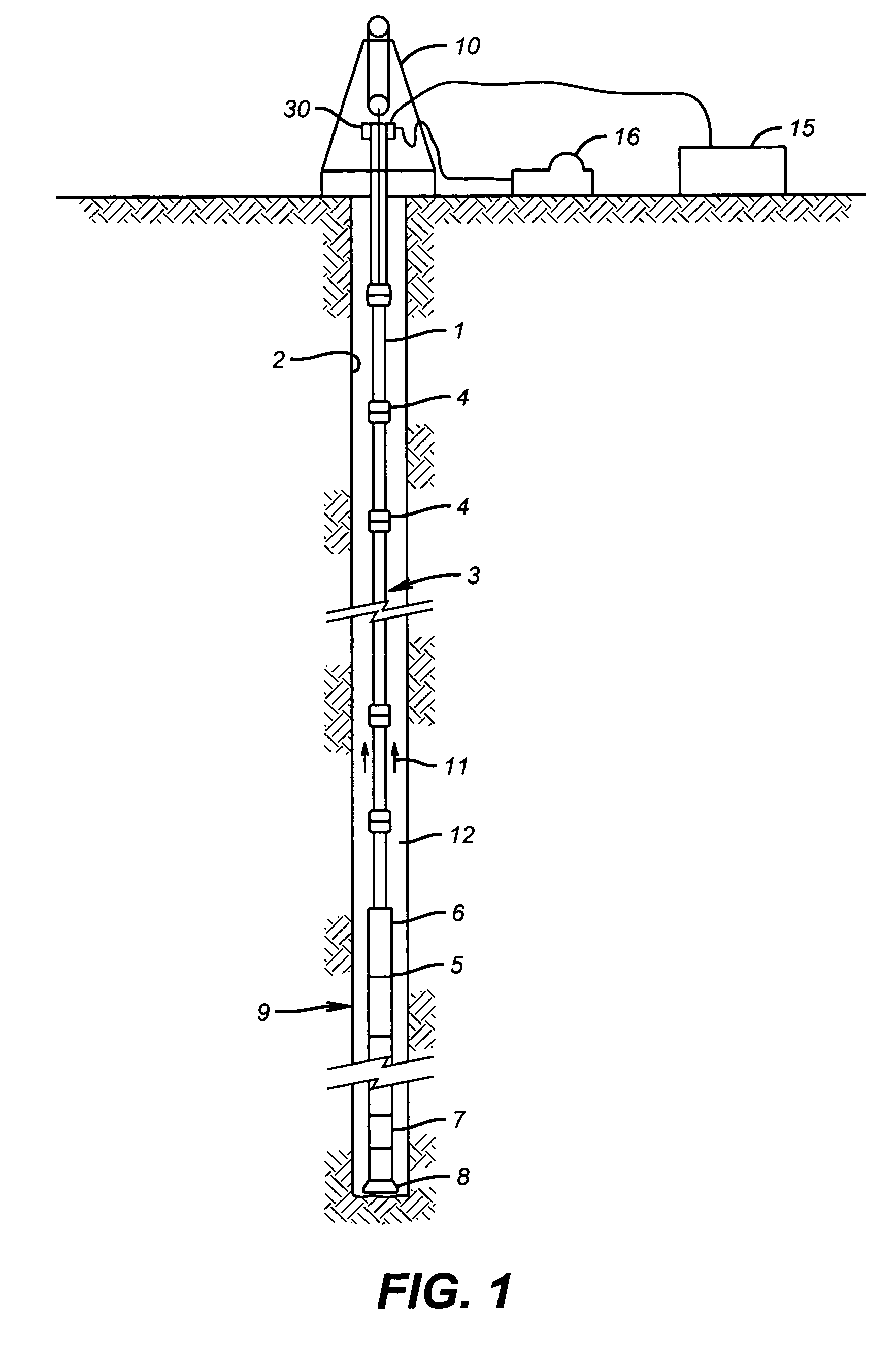
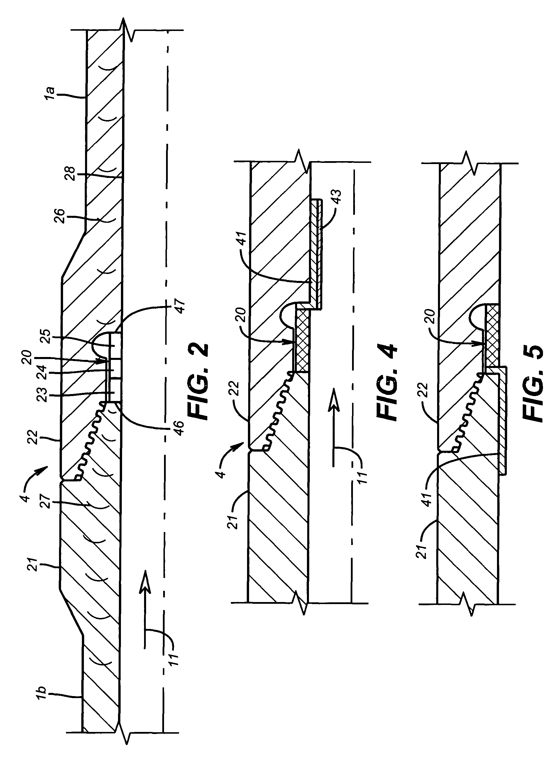
[0041]In one preferred embodiment, see FIG. 1, and described herein as an example and not as a limitation, a drilling operation has a conventional derrick 10 for supporting a drill string 3 in a borehole 2, also called a wellbore. Drill string 3 comprises multiple sections of drill pipe 1 connected together by threaded connections 4. A bottomhole assembly 9 is attached to the bottom end of drill string 3 and has a drill bit 8 attached to a bottom end thereof. Drill bit 8 is rotated to drill through the earth formations. Bottom hole assembly 9 comprises multiple sections of drill collars 6 and may have a measurement while drilling (MWD) system 7 attached therein, above bit 8. Drill collar sections 6 and MWD system 7 are connected through threaded connections 5. Measurement while drilling and / or logging while drilling (LWD) systems are well known in the art. Such systems commonly measure a number of parameters of interest regarding the drilling operation, the formations, surrounding t...


PUM


Abstract

A measurement and communication system for use with a tubular string, comprises a tubular string having a plurality of self-powered, autonomous telemetry stations disposed at predetermined locations along the tubular string. Each autonomous telemetry station is adapted to receive at least one first signal and transmit at least one second signal related to the at least one first signal. Power is extracted from potential energy sources proximate each autonomous telemetry station. A method of communicating information along a tubular string comprises, disposing an autonomous telemetry station at predetermined locations along the tubular string. A preferred transmission path is autonomously determined at each of the autonomous telemetry stations. Information is transmitted along the tubular string according to the autonomously determined preferred path.

Description

CROSS-REFERENCE TO RELATED APPLICATIONS[0001]This application claims the benefit of U.S. Provisional Application No. 60 / 478,237, filed Jun. 13, 2003, and of U.S. Provisional Application No. 60 / 491,567, filed Jul. 31, 2003.STATEMENT REGARDING FEDERALLY SPONSORED RESEARCH OR DEVELOPMENT[0002]Not applicableBACKGROUND OF THE INVENTION[0003]1. Field of the Invention[0004]This invention relates to transmission of information along a tubular string, and more particularly to a system of autonomous telemetry stations positioned along the tubular string for low-power, adaptive communication and measurement.[0005]2. Description of the Related Art[0006]The oilfield industry currently uses two extremes of communication within wellbores. The classification of these two extremes relate to the timing of the wellbore construction, typically during the wellbore construction and after construction during the operation of the wellbore for production of hydrocarbons.[0007]During the drilling and complet...

Claims


Application Information

Patent Timeline
Patent Type & Authority Patents(United States)
IPC IPC(8): G01V3/00E21B17/02E21B41/00E21B47/12E21B47/14E21B47/16G01V11/00
CPCE21B17/028E21B41/0085E21B47/122E21B47/123E21B47/14E21B47/16G01V11/002E21B47/13E21B47/135E21B47/18G01V11/00
Inventor FINCHER, ROGERARONSTAM, PETERWATKINS, LARRYGOLD, RANDY
Owner BAKER HUGHES INC
Learn More