Gear housing

a technology for gears and housings, applied in the direction of vehicle maintenance, vehicle cleaning, transportation and packaging, etc., can solve the problems of invariably costly and complicated production of profiled seals, laborious methods of fastening, and low production efficiency of cost-effective products

Active Publication Date: 2012-10-16
ROBERT BOSCH GMBH
View PDF13 Cites 27 Cited by
  • Summary
  • Abstract
  • Description
  • Claims
  • Application Information

AI Technical Summary

Benefits of technology

[0004]The problem addressed by the invention is to propose a gear housing which can be manufactured cost-effectively and in which a rigid connection is ensured between the housing base body and housing cover using fastening means which are little prone to damage.
[0005]The fundamental idea behind the invention is to combine spring-elastic retaining clips made of spring steel which are spaced apart over the circumference of the gear housing with a bearing region on the housing base body that is narrow in relation to the width of the seal. The provision of retaining clips made of spring steel (steel clips, retaining springs), which are designed in particular as separate components, ensures a rigid connection between the housing base body and housing cover. Furthermore, by contrast with plastic clips, retaining clips made of spring steel are not at risk of breaking, a factor which also makes mounting simpler or easier since the retaining clips do not need to be carefully handled and attention does not have to be paid to any possible damage of the retaining clips during mounting. Furthermore, the spring action of the retaining clips made of spring steel makes it possible to compensate for any manufacturing tolerances. The narrow bearing region, i.e. a bearing region having a small radial extension, has the advantage that savings can be made on the housing base body material, in particular aluminum, aluminum alloys or plastics, since the bearing region does not have to extend over the entire radial extension of the seal.
[0006]Owing to the saving on material, the housing base body, and hence the gear housing, can be produced cost-effectively while having sufficient stability. In the mounted state, the seal, by virtue of the seal compression, has a larger radial extension than in the non-mounted state. Preference is given to an embodiment in which the radial extension of the bearing region is even smaller than the radial extension of the seal in the non-mounted state.
[0009]The flat design of the ring seal side facing the housing base body makes it possible to manufacture the ring seal as a cost-effective extruded profile preferably having a rectangular cross-sectional area. However, it is also conceivable for the ring seal to be applied to the finished housing cover by injection molding.
[0011]The provision of at least one stop on the housing base body on which the housing cover bears, in particular by way of a supporting lug extending in the axial direction, makes it possible to achieve a defined compression of the ring seal, substantially independently of the size of the spring force of the retaining springs made of spring steel. The retaining springs just need to be dimensioned such that contact is ensured at all times between the housing cover and the at least one stop.
[0013]In order to be able to achieve a housing cover design which is as simple as possible, with the result that tooling costs are further reduced, an advantageous embodiment comprises designing the retaining clips in such a way that they directly exert a compressive force on the housing cover surface in the direction of the housing base body. In such an embodiment, latching projections on the cover for the retaining clips are preferably dispensed with.

Problems solved by technology

This method of fastening is laborious and requires a large number of mounting steps to attach the screws or rivets.
A disadvantage with this method is that the plastic clips which are used are prone to breaking and the profiled seal is invariably costly and complicated to produce.
This embodiment is advantageous in that ring seals without a sealing edge, which can be manufactured economically, can be used, but disadvantageous in that the plastic clips are prone to damage and do not always ensure sufficient seal compression.
Additionally known is the use of retaining clips made of spring steel, these only being used in combination with profiled seals having a sealing edge, such seals being complicated and costly to produce.
Consequently, the housing base body, at least in the contact region, must have a large radial extension which is actually not necessary for stability reasons, a situation which considerably increases the use of material and hence the manufacturing costs.

Method used


Image

  • Gear housing
  • Gear housing

Examples


Embodiment Construction

[0020]In the figures, identical components having the same function are denoted by the same reference numbers.

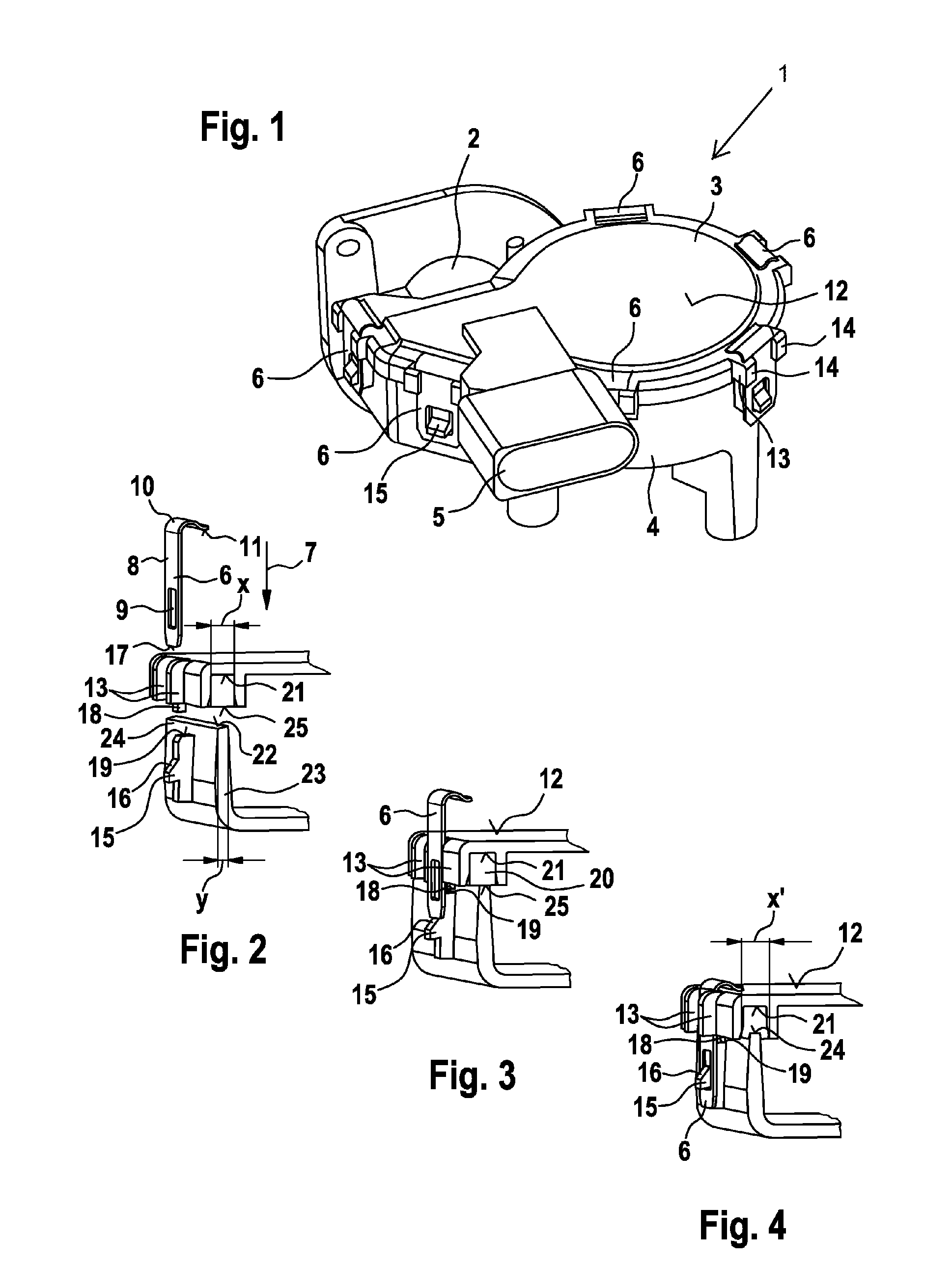
[0021]FIG. 1 shows a gear housing 1 of a wiper system (not shown) for a motor vehicle. The gear housing 1 contains a worm gear which is accommodated in a motor housing 2 flanged onto the gear housing 1. The gear housing 1 shown is usually secured to a vehicle body-mounted fastening tube (not shown either).

[0022]The gear housing 1 comprises an upper (in the plane of the drawing) housing cover 3 made of plastic and, connected thereto, a housing base body 4 made of die-cast aluminum. Arranged on the housing cover 3 is a coded connection socket 5 for receiving a plug connector (not shown), inter alia for supplying the drive motor arranged in the motor housing 2 with electric current.

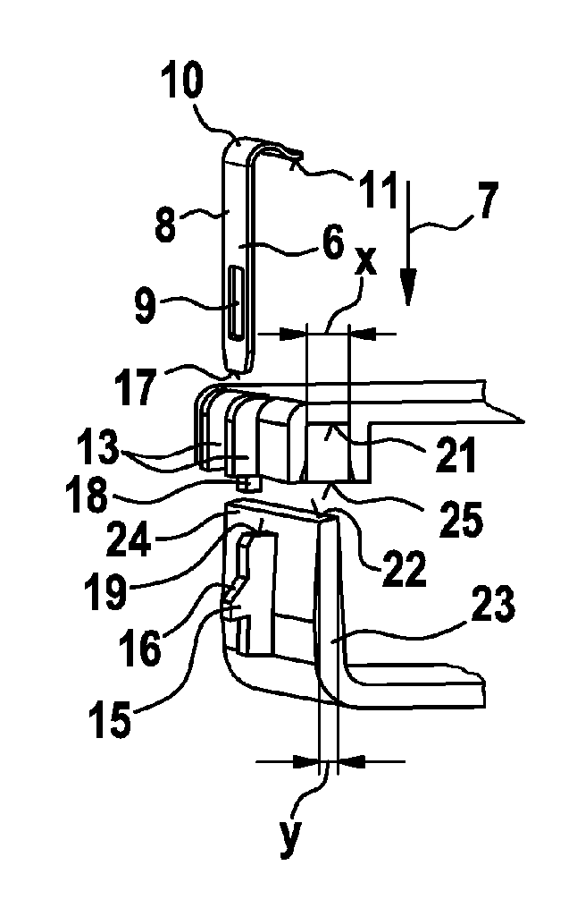
[0023]To secure the housing cover 3 to the housing base body 4, there is provided a plurality of retaining clips 6 made of spring steel which are spaced apart in the circumferential direction. Said c...


PUM


Abstract

The invention relates to a gear housing (1) comprising a gear, particularly comprising a gear of a wiper device for motor vehicles, having a housing base body (4), having a housing cover (3) affixed at a distance to the housing base body (4) by means of a plurality of retaining clips (6) made of spring steel in circumferential direction, and having an annular seal (20) disposed between the housing base body (4) and the housing cover (3) and pressed against a support region (24) of the housing base body. The invention provides that the radial extension (y) of the support region is smaller than the radial extension (x, x′) of the annular seal.

Description

BACKGROUND OF THE INVENTION[0001]The invention relates to a gear housing with a gear unit.[0002]Gear housings, in particular with an internal worm gear, having an electric drive motor flanged onto the gear housing and forming a constituent part of wiper systems for motor vehicles are known in a wide variety of designs.[0003]The known gear housings generally comprise two half-shells, namely a housing base body and a housing cover secured to the housing base body, with a ring seal being provided between the housing cover and housing base body to prevent moisture from entering the gear housing. It is known practice to provide screws or rivets to secure the housing cover to the housing base body, in which case the ring seal arranged between the housing cover and housing base body is designed as a flat seal. This method of fastening is laborious and requires a large number of mounting steps to attach the screws or rivets. In another known technique, a housing cover which is formed from p...

Claims


Application Information

Patent Timeline
Patent Type & Authority Patents(United States)
IPC IPC(8): F16H57/02F16H57/00F16H57/029F16H57/031F16H57/039
CPCB60S1/166F16H57/029F16H57/039F16H57/031Y10T74/2186F16H2057/0062F16J15/02B60S1/16
Inventor HURST, RICHARDSAUER, CHRISTIANHEYDER, MARTIN
Owner ROBERT BOSCH GMBH
Why Eureka
Try Eureka