Variable ratio hand pump

a hand pump and variable ratio technology, applied in the direction of piston pumps, positive displacement liquid engines, fluid couplings, etc., can solve the problems of premature failure, lateral loading of the compensation cylinder, etc., and achieve the effect of reducing the distance from the lever pivot and reducing the amount of for

Active Publication Date: 2012-10-16
ENERPAC TOOL GRP CORP
View PDF17 Cites 1 Cited by
  • Summary
  • Abstract
  • Description
  • Claims
  • Application Information

AI Technical Summary

Benefits of technology

[0006]The present invention provides a hand operated hydraulic pump in which the lever pivot is to a cam. The cam is pivoted, at a distance away from the lever pivot, to the housing of the pump. The compensation cylinder, which is subjected to the output pressure of the pump, acts on the cam to rotate the cam above the housing pivot so as to reduce the distance from the lever pivot to the pump plunger as the output pressure of the pump increases. This reduces the moment arm between the lever pivot and the pump plunger, which has the effect of reducing the amount of force required to be exerted by the user on the handle of the lever to produce any given pump output pressure.
[0007]In a preferred aspect, the cam pivots are arranged in a manner so that operating the lever at a low pressure tends to maximize the distance between the lever pivot and the pump plunger, so as to maximize flow rate for lower pressures. In addition, the compensation device is preferably biased in this direction.

Problems solved by technology

Such systems result in lateral loading on the compensation cylinder and premature failure.

Method used


Image

  • Variable ratio hand pump
  • Variable ratio hand pump

Examples


Embodiment Construction

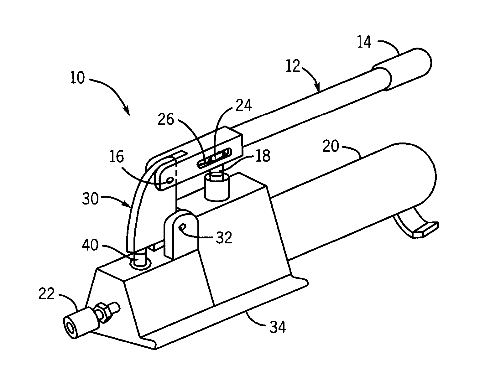
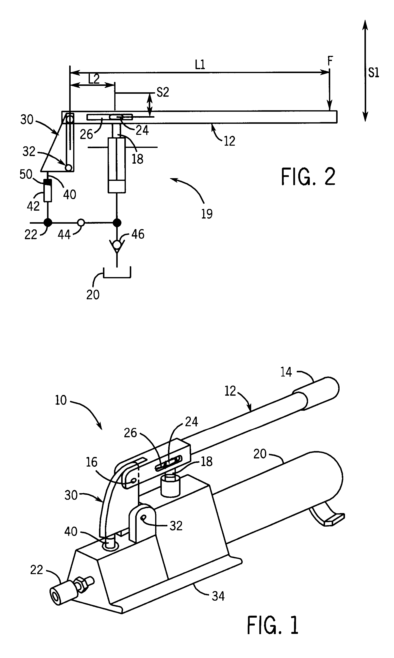
[0011]Referring to FIG. 1, a hand operated hydraulic pump 10 of the invention has a lever 12 with a handle 14 and a pivot 16. The lever 12 is operable by handle 14 to pivot back and forth about pivot 16 to reciprocate plunger 18 of a pumping unit 19 of the pump 10 so as to pump hydraulic fluid out of reservoir 20 to pressure port 22. Plunger 18 extends through a slot in the bottom of lever 12 and has a head 24 that reciprocates back and forth in slot 26 as the lever 12 is pivoted up and down. Hydraulic hoses or other lines can be connected to pressure port 22 so as to provide hydraulic fluid under pressure to a load such as a hydraulic cylinder and return hydraulic fluid to the reservoir 20 from the load upon the actuation of a return valve (not shown).

[0012]The lever 12 is pivoted at pivot 16 to a cam 30 which is pivoted at pivot 32 to housing 34 of the pump 10. Pivot 32 is spaced below pivot 16 and may be slightly toward plunger 40 so that as the lever 12 is operated, when pushing...


PUM


Abstract

A hand operated hydraulic pump has a cam that is pivoted by a compensation cylinder that rotates the cam so as to move the pivot of an operating handle closer to the pump plunger as the output pressure of the pump increases.

Description

CROSS-REFERENCE TO RELATED APPLICATION[0001]This application claims the benefit of PCT International Application No. PCT / US2008 / 054211 filed on Feb. 18, 2008, which claims the benefit of U.S. Provisional Patent Application No. 60 / 890,557 filed on Feb. 19, 2007, which is incorporated by reference herein.STATEMENT CONCERNING FEDERALLY SPONSORED RESEARCH OR DEVELOPMENT[0002]Not applicable.FIELD OF THE INVENTION[0003]This invention relates to hydraulic hand pumps and in particular to hand pumps that vary the lever pivot point dependent on output pressure of the pump.BACKGROUND OF THE INVENTION[0004]Hydraulic hand pumps in which a hand operated lever is pivotable against a plunger of a pump, which may be either a two stage or a single stage pump, are well known. In most such pumps, the pivot point of the lever is fixed regardless of the output pressure of the pump. However, it has been recognized that reducing the distance between the lever pivot point and pump plunger reduces the amount...

Claims


Application Information

Patent Timeline
Patent Type & Authority Patents(United States)
IPC IPC(8): F04B25/00F04B49/00F04B5/00F04B3/00
CPCF04B9/14
Inventor WEBER, FREDERICUS JOHANNES
Owner ENERPAC TOOL GRP CORP
Why Eureka
Try Eureka