Reconfigurable inductive to synchronous motor
a synchronous motor and inductive technology, applied in the direction of windings, magnetic circuit rotating parts, magnetic circuit shapes/forms/construction, etc., can solve the problems of low power induction motors that are not highly efficient, lose efficiency under reduced loads, and limit the size of permanent magnets, etc., to achieve high efficiency synchronous operation, strong magnetic field, and efficient synchronous operation
- Summary
- Abstract
- Description
- Claims
- Application Information
AI Technical Summary
Benefits of technology
Problems solved by technology
Method used
Image
Examples
first embodiment
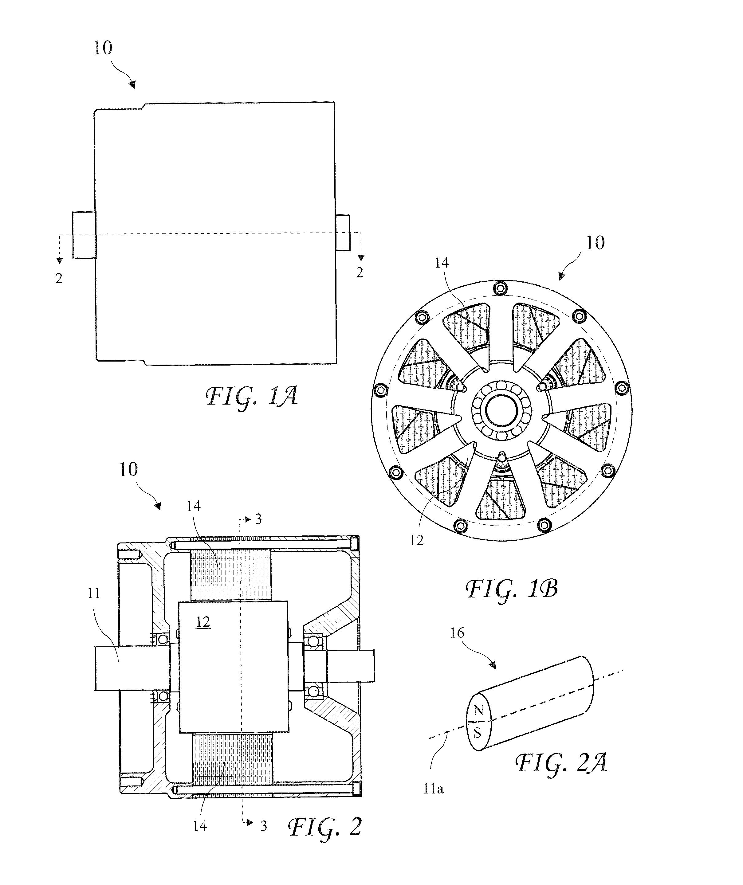
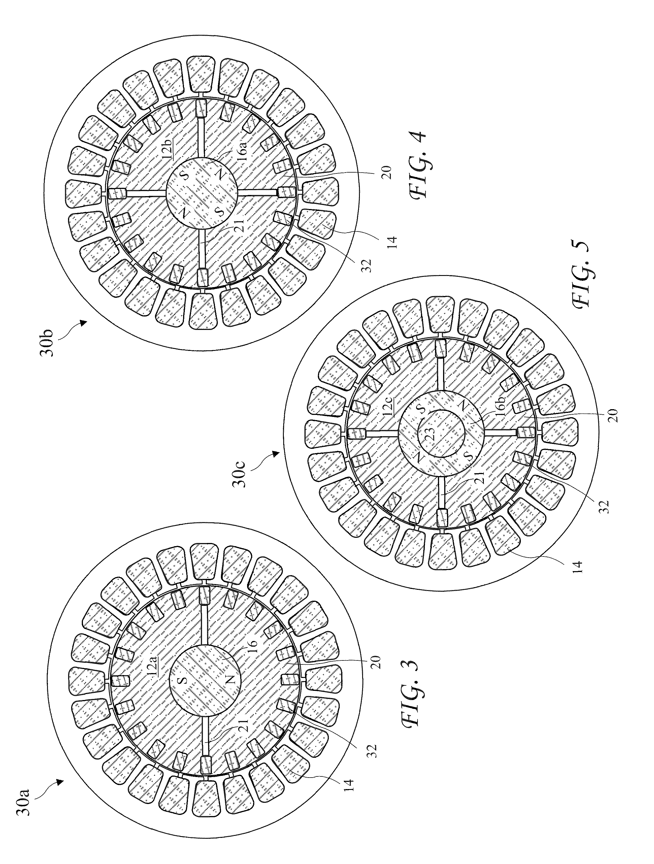
[0071]A cross-sectional view of the reconfigurable electric motor 10 taken along line 3-3 of FIG. 2 showing the motor 10 comprising a two pole motor 30a with a single two pole rotatable Interior Permanent Magnet (IPM) 16 in the rotor 12a is shown residing coaxial with the motor shaft 11 in FIG. 3. The magnet 16 is shown with air gaps 21 on each side of the magnet 16 splitting the North (N) and South (S) poles of the magnet 16 in a radially aligned configuration. Bars 32 of a squirrel cage element for inductive operation are angularly spaced apart around the outer radius of the rotor 12 reaching the length of the rotor 12. The bar may be straight or may be twisted to reduce noise among other benefits. The magnet 16 and rods 32 are carried by rotor pole pieces 20 separated by the air gaps 21. The pole pieces 20 are preferably constructed from laminated layers of individually insulated magnetically conducting material, for example, iron or steel.
second embodiment
[0072]A cross-sectional view of the reconfigurable electric motor 10 according to the present invention taken along line 3-3 of FIG. 2 showing the motor 10 comprising a four pole motor 30b with a single four pole rotatable permanent magnet 16a residing coaxial with the motor shaft 11 in a radially aligned rotor 12b configuration is shown in FIG. 4. The pole piece 20 is divided into four quarter sections with air gaps 21 between adjacent sections. The motor 30b is otherwise like the motor 30a.
third embodiment
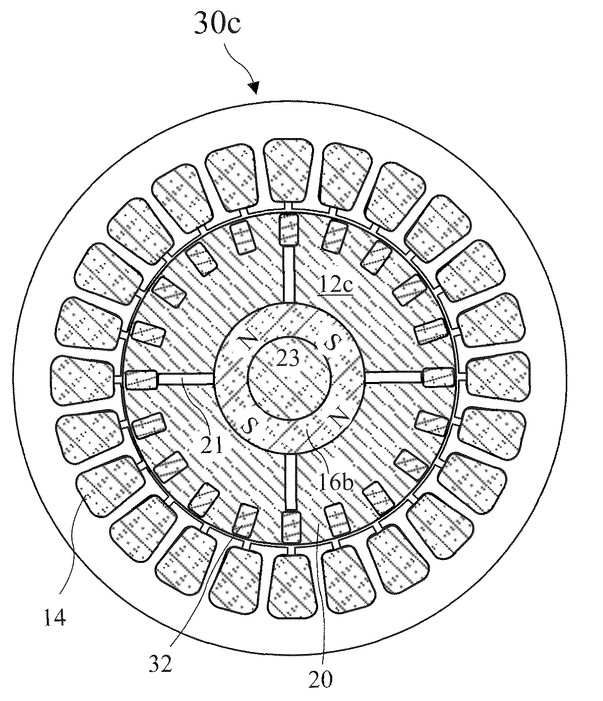
[0073]A cross-sectional view of the reconfigurable electric motor 10 according to the present invention taken along line 3-3 of FIG. 2 showing the motor 10 comprising a four pole motor 30c with a rotor 12c having a single hollow four pole rotatable permanent magnet 16b residing coaxial with the motor shaft 11 in a radially aligned rotor configuration is shown in FIG. 5. A steel shaft 23 runs through the center of the hollow magnet 16b. The motor 30c is otherwise like the motor 30b.
[0074]A perspective view of a cylindrical two pole permanent magnet 16 suitable for use with the present invention is shown in FIG. 2A. The magnet 16 has a magnet axis 11a. While a cylindrical magnet is a preferred shape for a rotating magnet according to the present invention, other shapes may be adapted to be moveable to obtain the benefit of the present invention and an electric motor having moveable magnets of any shape configured to adjust a rotor magnetic field to a weak magnetic field for asynchron...
PUM
 Abstract
Description
Claims
Application Information
 - R&D
- Intellectual Property
- Life Sciences
- Materials
- Tech Scout
- Unparalleled Data Quality
- Higher Quality Content
- 60% Fewer Hallucinations
Browse by: Latest US Patents, China's latest patents, Technical Efficacy Thesaurus, Application Domain, Technology Topic, Popular Technical Reports.
© 2025 PatSnap. All rights reserved.Legal|Privacy policy|Modern Slavery Act Transparency Statement|Sitemap|About US| Contact US: help@patsnap.com


