Illuminated suction apparatus

a suction device and illumination technology, applied in the field of surgical illumination, can solve the problems of poor quality or poorly directed illumination, static and poorly directed light emanating from an operating microscope, and insufficient lighting from either source, so as to reduce reflected glare, improve illumination, and reduce the effect of scattering coefficien

Active Publication Date: 2012-10-23
INVUITY
View PDF25 Cites 43 Cited by
  • Summary
  • Abstract
  • Description
  • Claims
  • Application Information

AI Technical Summary

Benefits of technology

[0007]The illuminated suction apparatus includes suction and illumination functions integrated into a hand-held device suited to meet the ergonomic needs of the physician. The hand-held, repositionable suction function already prevalently used in surgical procedures is surrounded by an illuminated waveguide which enables the physician to apply lighting directly to the desired region of the anatomy below the skin regardless of incision angle, depth, and surrounding anatomical obstructions. The illumination waveguide is a solid structure designed to specifically guide light from a high-intensity light source and is fabricated using an optical-grade polymer with a specific index of refraction such as cyclo-olefin polymer or copolymer or any other suitable acrylic or plastic. Furthermore, the illumination waveguide can be engineered to efficiently transmit light from its distal output by sheathing or surrounding it with a second material of lower index of refraction properly coordinated to the index of refraction of the core material to preserve Total Internal Reflection (TIR). This solid-state, structure guided illumination waveguide is powered via a fiber optic cable connected to a high intensity light source such as 300W xenon sources supplied by Luxtec, BFW, and others.
[0009]The use of a generally solid waveguide for suction illumination, rather than optical fibers, eliminates losses due to the non-transmissive spaces between the optical fibers and reduces losses solely to those associated with Fresnel reflections. The marked reduction in losses associated with a fiber / fiber junction allows for high intensity light transmission to the waveguide without significant heating of the interface or need for heat sink devices or mechanisms at the interface. With a fiber to waveguide connection, light from a standard 300 watt light source can be transmitted with use of standard connectors such as ACMI, with a steady state temperature below the temperatures harmful to body tissue without design alteration.
[0010]Use of total internal reflection and light mixing in an illumination waveguide enables control of the output light profile and enables custom illumination profiles. Microstructures can be applied to any suitable surfaces of the illumination waveguide and light can be extracted incrementally along the walls of the device with injection molded structures and other suitable structures at minimal added cost. Use of sequential extraction surfaces, changes in the numerical aperture of the device as a function of position, use of extraction structures—either micro or macro structural, with or without changes in the numerical aperture, selective cladding, selective reflective coatings, etc, all can be used to shape the output profile of the waveguide to meet the design specifications or light specifications requested by the user for specific surgical suction illumination applications.
[0011]The device is meant to be disposable, fabricated out of low cost materials to enable leverage of manufacturing efficiencies through use of processes such as high-volume injection molding, over-molding, and metal & polymer extrusion. Device assembly would be engineered to minimize labor costs. A low cost, high-performance combination device provides an attractive alternative to existing discrete illumination and suction devices while minimizing incremental cost to the user.
[0014]In an alternate configuration, the distal tip of the suction tube may be configured to transmit light or reflect light such that the surgeon sees the distal tip of the suction as illuminated such that he / she can localize the distal tip of the suction device in their peripheral vision without directly looking at or focusing on the tip of the device. Extending a thin layer of the waveguide to the tip can provide the effect. Strategies that implement this effect include but are not limited to: (a) waveguide extended to the tip with or without surface extraction features to cause light to back reflect or scatter off the tip, (b) Use of a thin layer of optically transmissive material with high scattering coefficient to cause the suction device to glow (c) reflective surfaces applied to the outside of the central suction device (d) reflective surfaces applied with imperfections on the surface to reflect or scatter the light off the outer surface (e) use of a cladding material applied to the walls of the inner suction tube that transmits or scatters a portion of the output light, the input to the cladding being either an imperfection in the cladding or naturally occurring leakage, (f) fluorescent coating on the tip, (g) phosphorescent coatings (h) use of embedded or graded reflectors along or at the tip of the device. Alternatively, the distal tip geometry could be formed to intentionally scatter light (square edges, etc).
[0015]One or more surfaces in an optical waveguide sheath or adapters or connectors may be polarized using any suitable technique such as micro-optic structure, thin film coating or other. Use of polarized light in a surgical environment may provide superior illumination and coupled with the use of complementary polarized coatings on viewing devices such as cameras or surgeon's glasses may reduce reflected glare providing less visual distortion and more accurate color rendering of the surgical site. One or more surfaces of an optical waveguide sheath may also include light filtering elements to emit light of one or more frequencies that may enhance visualization of specific tissues.

Problems solved by technology

There are scenarios in which these illumination sources provide lighting that is either poor in quality or poorly directed.
Light emanating from an operating microscope is static and may be poorly directed relative to the angle of surgical access.
Lighting from either source may not be adequate as the physician progresses through various phases of the procedure requiring visualization of the anatomy at varied depths from the skin-level incision.
These devices face multiple challenges.
These assemblies, with limited cross section, are only capable of transmitting less than 50% of the output light from a standard 5 mm fiber optic cable attached to standard light sources in the operating room.
Inefficiencies in the fiber-to-fiber coupling with high intensity light leads to light losses at the interface which produces heat.
The spatial zones between the fibers are frequently the dominant cause of light loss and heat.
Excess heat at the interface can cause thermal damage to the tissues and is also a fire hazard in the operating room.
Due to the fiber / fiber interface concerns, some manufacturers have produced more expensive devices in which the connection is eliminated and the entire fiber optic bundle acts as the surgical light source.
In surgery, when using a suction illumination device in which the output light emanates from a point proximal to the distal end of the device, a surgeon may experience difficulty.
The problem is that while focused on the surgical field the surgeon uses the central portion of the visual field produced by rods for the high acuity work, the brain misinterprets the location of the light source in the periphery of the visual field as the location of the distal tip of the suction device.

Method used


Image

  • Illuminated suction apparatus
  • Illuminated suction apparatus
  • Illuminated suction apparatus

Examples


Embodiment Construction

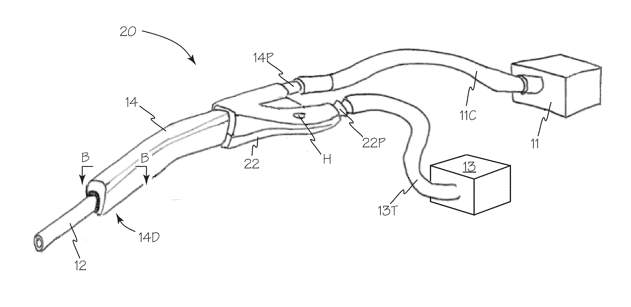
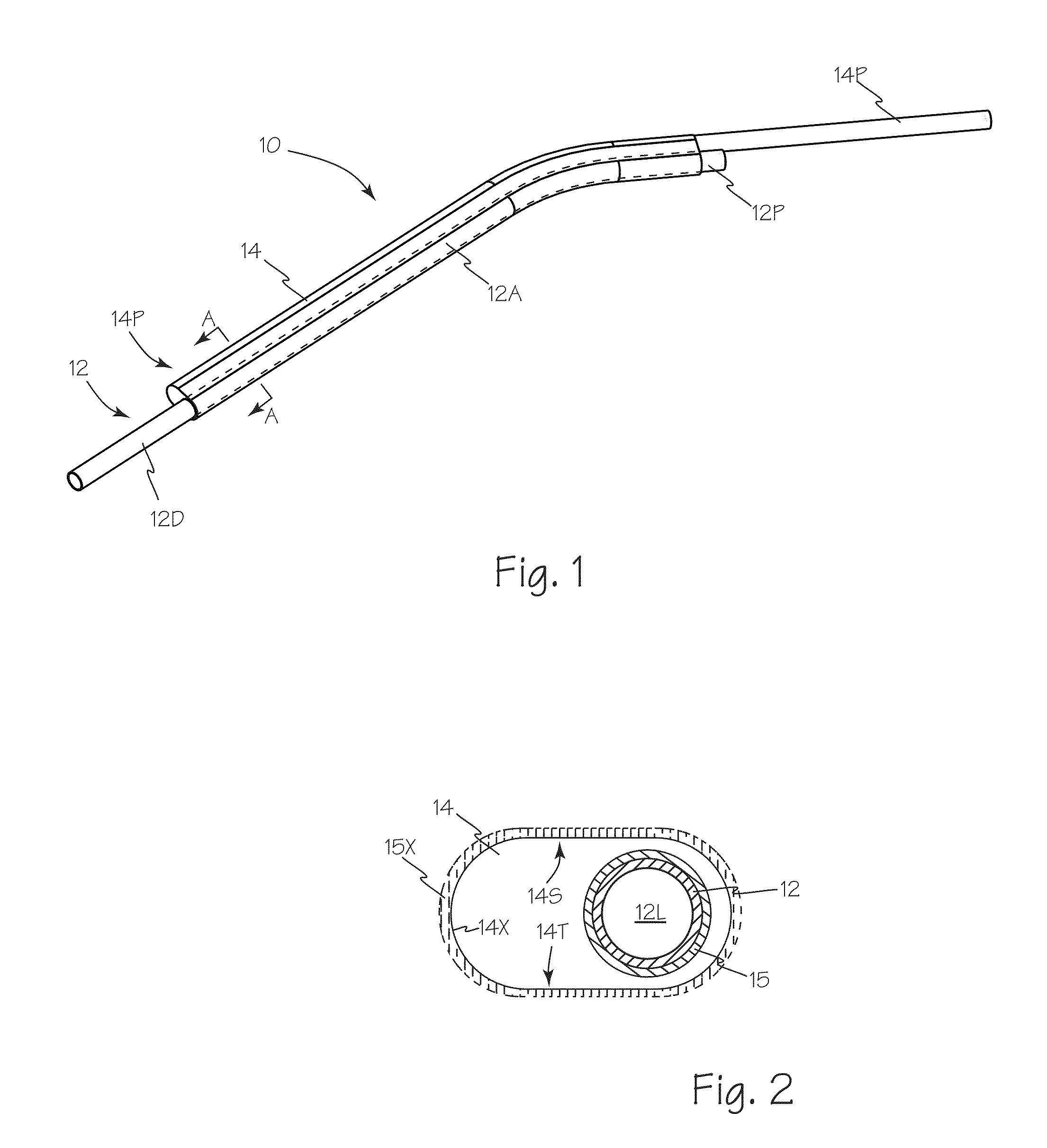
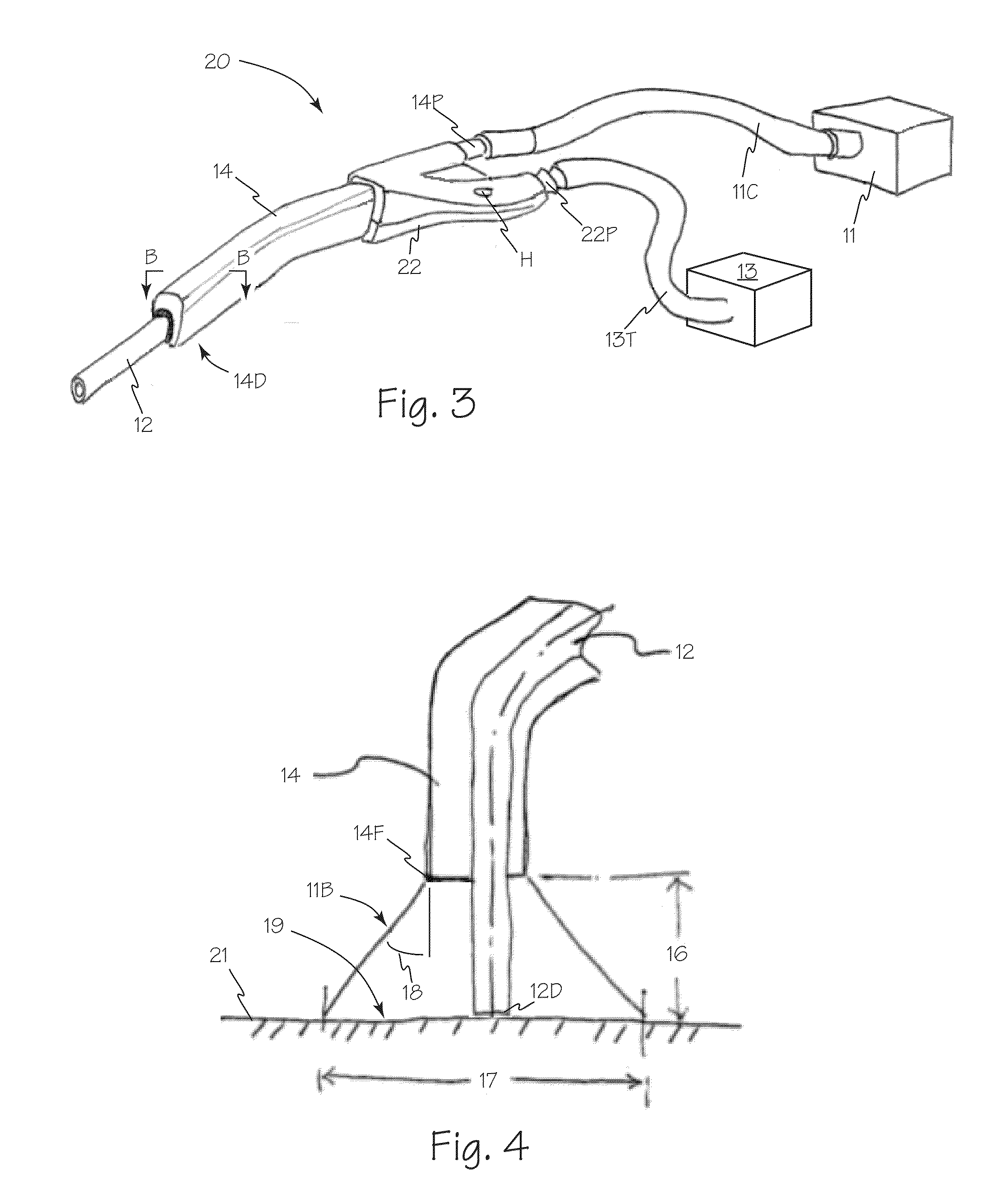
[0031]Referring to FIGS. 1 and 2, illuminated suction apparatus 10 includes suction tube 12 made of any suitable material such as aluminum, stainless steel or any suitable acrylic or other polymer. Suction tube 12 encloses suction lumen 12L. Illumination waveguide 14 is secured over cladding layer 15 on central portion 12A of suction tube 12 leaving input or proximal portion 12P and distal portion 12D exposed. Illumination waveguide 14 may have a flat side such as side 14S or side 14T to optimize light mixing as light 11L travels from illuminator input 14P to output 14D.

[0032]Illumination waveguide 14 is made of an optical grade engineering thermoplastic such as cyclo olefin polymer which efficiently transmits light. Any other suitable material such as Cyclic Olefin Copolymer, Polycarbonate, Acrylic and or TPC may also be used. The angles and bends of the waveguide structure are engineered so light transmits through the waveguide via TIR. The side walls and other features have angle...


PUM

PropertyMeasurementUnit
refractive indexaaaaaaaaaa

Abstract

An illuminated suction apparatus including a hand-held surgical device combining a high-performance illumination waveguide with suction. This device would be useful in a wide array of various surgical procedures including open and minimally invasive orthopedics.

Description

FIELD OF THE INVENTIONS[0001]The present invention relates generally to the field of surgical illumination and more specifically to illumination systems with integrated surgical tools.BACKGROUND OF THE INVENTIONS[0002]In various surgical procedures, illumination of the surgical field is typically achieved through the use of headlamps and surgical microscopes. There are scenarios in which these illumination sources provide lighting that is either poor in quality or poorly directed. As an example, during spinal surgery from the lumbar approach, access to the desired anatomical target area may be achieved through an angled incision on one side of the patient's midline. Light emanating from an operating microscope is static and may be poorly directed relative to the angle of surgical access. Conversely, light from a headlamp may be adjusted as a physician tilts or moves his head to redirect the output beam, but still may be blocked by various anatomical structures such as the spinous pr...

Claims


Application Information

Patent Timeline
Patent Type & Authority Patents(United States)
IPC IPC(8): A61B1/06
CPCA61B1/0017A61M1/0041A61M1/008G02B23/2469A61B1/07A61B19/5202A61M1/0047B29C65/08B29C65/48B29C65/58B29C66/71B29K2069/00B29K2055/02A61B90/30A61M1/7411A61M1/84A61M1/76A61B90/36B29K2067/046
Inventor VAYSER, ALEXERISMANN, FERNANDOTRAUNER, KENNETH B.GASSON, JONATHANRICHARDSON, DERRICK
Owner INVUITY
Why Eureka
Try Eureka