Dimming electronic ballast with preheat current control

a technology of electronic ballast and control current, which is applied in the field of electronic ballast, can solve the problems of affecting the life of lamps, difficult circuit design, and inability to contribute to light output, so as to prevent the short life of lamps, reduce the effect of power consumption and efficient conversion

Inactive Publication Date: 2012-10-23
PANASONIC CORP
View PDF14 Cites 9 Cited by
  • Summary
  • Abstract
  • Description
  • Claims
  • Application Information

AI Technical Summary

Benefits of technology

[0033]Meanwhile, in the electronic ballast described as the second conventional example, the constant preheating current is stopped after achieving stable lighting, thereby eliminating the concern considered as a problem in the first conventional example about power loss without contributing to a light output and adverse effects to the lamp life. However, this configuration will result in having an insufficient preheating current because no constant preheating current is supplied during dimming control, and there is another concern about adverse effects such as premature filament failure.
[0034]The present invention was achieved by taking the above problems into consideration, having an object to improve efficiency of an electronic ballast by cutting off an unnecessary constant preheating current in a full-lighting mode and thereby reducing power loss which does not contribute to a light output. The invention also prevent problems related to a short life of a discharge lamp such as premature filament failure by maintaining an appropriate filament temperature during lighting resulting from securing a constant preheating current in a dimming control mode with a reduced light output.
[0038]A fourth aspect of the present invention is based on the electronic ballast according to any one of the first to third aspects and makes it possible to realize a light output control over a plurality of stages with a visually continuous dimming operation. The amount of a preheating current is controlled in accordance with a lighting mode by changing the switch Q4 to operate corresponding to a lighting control signal or a signal secondarily generated from the lighting control signal as shown in FIG. 7.
[0040]According to the first and second aspects of the present invention, a power loss without contributing to a light output due to a constant preheating current flowing into filaments serving as a current path can be reduced in a lighting mode with a large light output in which an appropriate filament temperature can be maintained by a lamp current. An appropriate filament temperature can be maintained by securing the constant preheating current flowing into the filaments serving as a current path in a lighting mode with a small light output in which an appropriate filament temperature cannot be maintained only by a lamp current, so that problems related to premature filament failure (i.e. short life of lamp) can be prevented.
[0041]According to the third aspect of the present invention, power consumption can be efficiently converted into a light output and filament overheating can also be prevented in a first lighting mode. This prevents blackening of the lamp bulb, premature filament failure, and premature emitter exhaustion. Meanwhile, in a second lighting mode to obtain power saving and lighting effects by suppressing power consumed in a lamp, these effects can be obtained while preventing premature blackening of the lamp bulb, filament failure, and emitter exhaustion.
[0042]According to the fourth aspect of the present invention, it is possible to establish any amount of a filament current in accordance with the degree of a dimming control for a lamp without requiring an operation performed for a constant preheating current by a resonance effect, thereby making it easier to design a circuit for supplying preheating power.

Problems solved by technology

In the electronic ballast described as the first conventional example, a lighting output and a constant preheating current are appropriately supplied as stated above by a combination of the two independent resonant circuits including a main resonant circuit for supplying lighting power and a preheating resonant circuit for supplying filament preheating power, and the interrelationship therebetween is largely affected by variations in the characteristics of components which constitute the resonant circuits, thereby making it difficult to design the circuits.
In this case, a current which makes little difference to a current in a dimming control state is made to flow into filaments even in a full-lighting mode in which a constant preheating current is unnecessary, causing concern about an increased power loss without contributing to a light output and adverse effects to a lamp life.
However, this configuration will result in having an insufficient preheating current because no constant preheating current is supplied during dimming control, and there is another concern about adverse effects such as premature filament failure.

Method used


Image

  • Dimming electronic ballast with preheat current control
  • Dimming electronic ballast with preheat current control
  • Dimming electronic ballast with preheat current control

Examples


Embodiment Construction

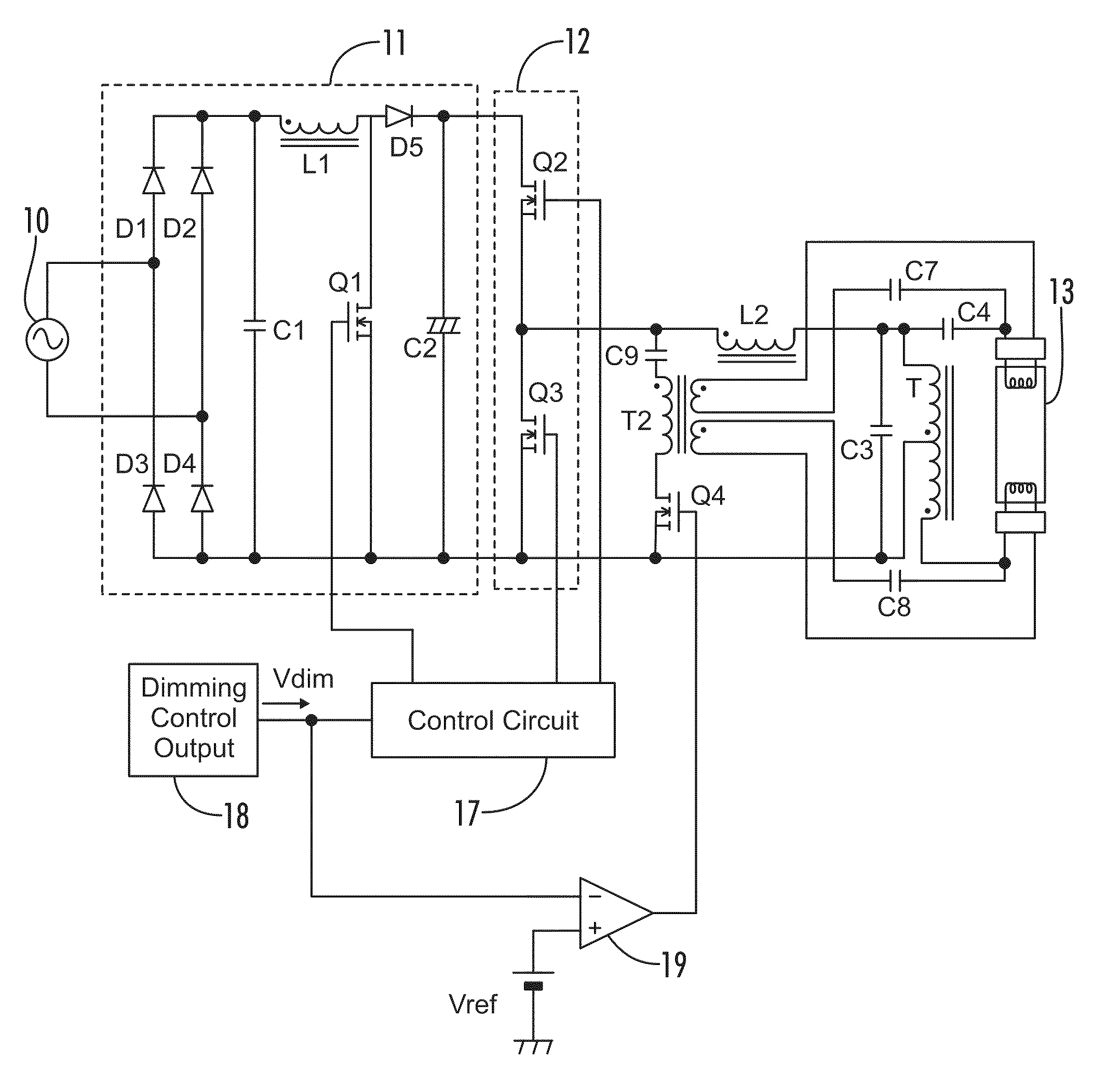
[0056]Shown in FIG. 1 is a circuit configuration of an electronic ballast according to a first embodiment of the invention to explain the configuration and operation thereof.

[0057]In this embodiment, an AC voltage of 100V and 50 / 60 Hz supplied from a commercial power source 10 is rectified to a DC voltage with a peak value of about 141V by a diode bridge including diodes D1 to D4. The DC voltage is stepped up by a step-up chopper circuit including a choke coil L1, a transistor Q1 and a diode D5. Obtained at both ends of an electrolytic capacitor C2 connected to an output end of the step-up chopper circuit is a DC voltage of, for example, about 300V. This DC voltage is converted into high frequency power in a subsequent inverter 12 and used as lighting power for a discharge lamp 13.

[0058]The inverter 12 has a half bridge inverter circuit including serially connected transistors Q2 and Q3, and provides a high frequency rectangular wave voltage at a connection point between the switchi...


PUM


Abstract

An electronic ballast is capable of realizing high frequency lighting of a discharge lamp and switching between at least two lighting modes with different light outputs. The ballast includes a preheating circuit having a winding component connected in parallel with a main resonant circuit with a lamp current flowing therein for the discharge lamp. A constant preheating current for the lamp filaments is supplied from a secondary winding of the winding component during lighting of the discharge lamp and a path of a current flowing on a primary winding side of the winding component is switched by a switch according to the lighting mode.

Description

[0001]A portion of the disclosure of this patent document contains material that is subject to copyright protection. The copyright owner has no objection to the reproduction of the patent document or the patent disclosure, as it appears in the U.S. Patent and Trademark Office patent file or records, but otherwise reserves all copyright rights whatsoever.CROSS-REFERENCES TO RELATED APPLICATIONS[0002]This application claims benefit of the following patent application(s) which is hereby incorporated by reference: Japanese Patent Application No. JP2008-215809, filed Aug. 25, 2008.STATEMENT REGARDING FEDERALLY SPONSORED RESEARCH OR DEVELOPMENT[0003]Not ApplicableREFERENCE TO SEQUENCE LISTING OR COMPUTER PROGRAM LISTING APPENDIX[0004]Not ApplicableBACKGROUND OF THE INVENTION[0005]The present invention relates to an electronic ballast for a discharge lamp having at least two lighting modes with different light outputs, and a lighting fixture using such ballast.[0006]In a discharge lamp of ...

Claims


Application Information

Patent Timeline
Patent Type & Authority Patents(United States)
IPC IPC(8): H05B41/16
CPCH05B41/295H05B41/3925
Inventor MATSUDA, KENJI
Owner PANASONIC CORP
Why Eureka
Try Eureka