
Rotationally asymmetric chaotic optical multi-pass cavity

a multi-pass cavity, asymmetric technology, applied in the direction of optical radiation measurement, instruments, spectrometry/spectrophotometry/monochromators, etc., can solve the problem of invulnerability of high-condensity rigid cell structure, achieve high mechanical/temperature stability, facilitate manufacturing process, and simple structure

Active Publication Date: 2012-10-23
THE TRUSTEES FOR PRINCETON UNIV
View PDF24 Cites 4 Cited by
  • Summary
  • Abstract
  • Description
  • Claims
  • Application Information

AI Technical Summary

Benefits of technology

[0011]The present invention relates to a rotationally asymmetric chaotic cavity that consists of a single closed reflecting surface. The cavity is based on quasi-chaotic ray dynamics in a 3-dimensional (3-D) deformed sphere. Within a small volume cavity, light can trace out a long optical path length with little beam overlap. The present invention has a simple structure and high mechanical / temperature stability, thus greatly facilitating the manufacturing process and yielding considerable cost savings. Compared to existing multi-pass cells, the chaotic multi-pass cell of the present invention has a much simpler, more compact, and more robust structure, and the manufacturing cost of such a cell is greatly reduced due to the compact structure. Therefore, systems of the present invention are suitable for low cost, compact, and portable gas sensing applications. An immediate application of the invention is for trace gas detection. Additional applications of the invention include optical amplifiers and optical delay lines.
[0012]Devices in accordance with a present invention comprise a number of useful features and advantageous performance characteristics. For example, the 3-D cavity is composed of a single closed reflecting surface rather than several separate reflecting mirrors currently used in multi-pass cells, and has no rotational symmetry. The cavity of the present invention can support chaotic or quasi-chaotic ray dynamics, and, in the phase space, the reflection points of the trajectory are confined inside some specific regions within hundreds of spatially separated reflections. In addition, the highly compact rigid cell structure is invulnerable to relative movement of the cavity shells and insensitive to temperature variations. Furthermore, the rotationally unsymmetrical cavity surface can self-focus the circulating beam with a global focus point, making the beam size small even after hundreds of reflections, so the light beam can exit the cavity through an optical port, which may also serve as the input hole. For the cavity of the present invention, the beam spots may spread out on the cavity surfaces, with sufficient space between the nearest spots and the optical port, to reduce beam overlap on the cavity surfaces in order to decrease the interference fringes. Still further, the cell volume for cavities of the present invention may be one magnitude smaller than current art devices. Due to the small volume, the cell can respond promptly to gas flows, thus greatly facilitating real-time gas measurement. Still further, the cell can support meter-scale optical path lengths with a centimeter size cavity diameter. It has been calculated that the cell can achieve at least a 16-meter optical path length with a mean cell radius of 2.54 cm.
[0013]Exemplary cells of the present invention are also easy to align without adjusting the relative distances between the two cavity shells and easy to manufacture due to the simple structure. The cell may be made of metal, alloy, plastic or other materials using standard milling technologies, yielding considerable cost savings. In addition, different incidence angles can lead to different path lengths even for the same cavity, which is useful, as different sensing applications may require different path lengths. Moreover, the cell design is very flexible, where, by changing the deformation parameters or the aspherical shapes, the cavity can achieve different multi-pass properties according to the requirements of the specific applications.

Problems solved by technology

In addition, the highly compact rigid cell structure is invulnerable to relative movement of the cavity shells and insensitive to temperature variations.

Method used


Image

  • Rotationally asymmetric chaotic optical multi-pass cavity
  • Rotationally asymmetric chaotic optical multi-pass cavity
  • Rotationally asymmetric chaotic optical multi-pass cavity

Examples


examples

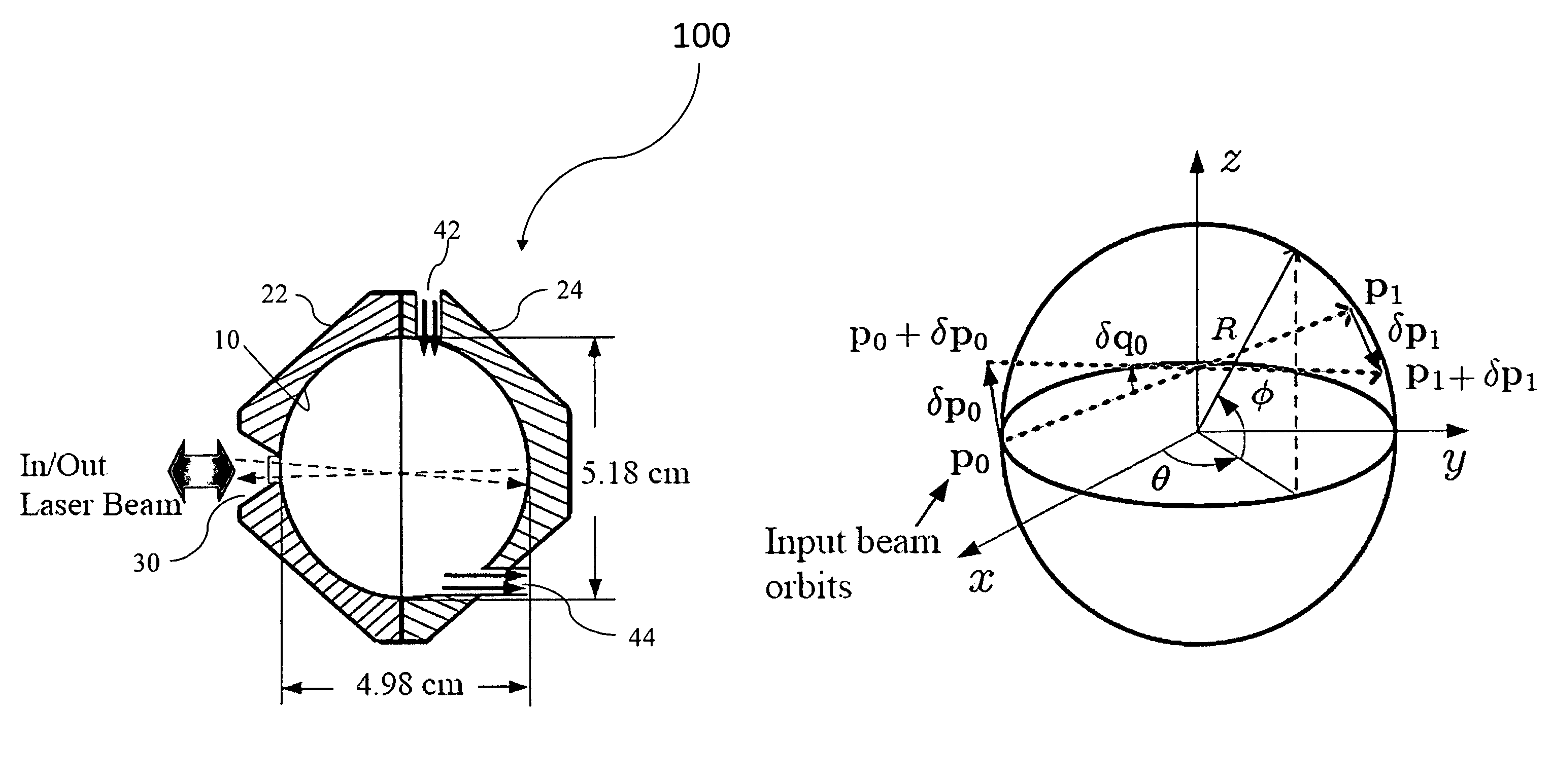
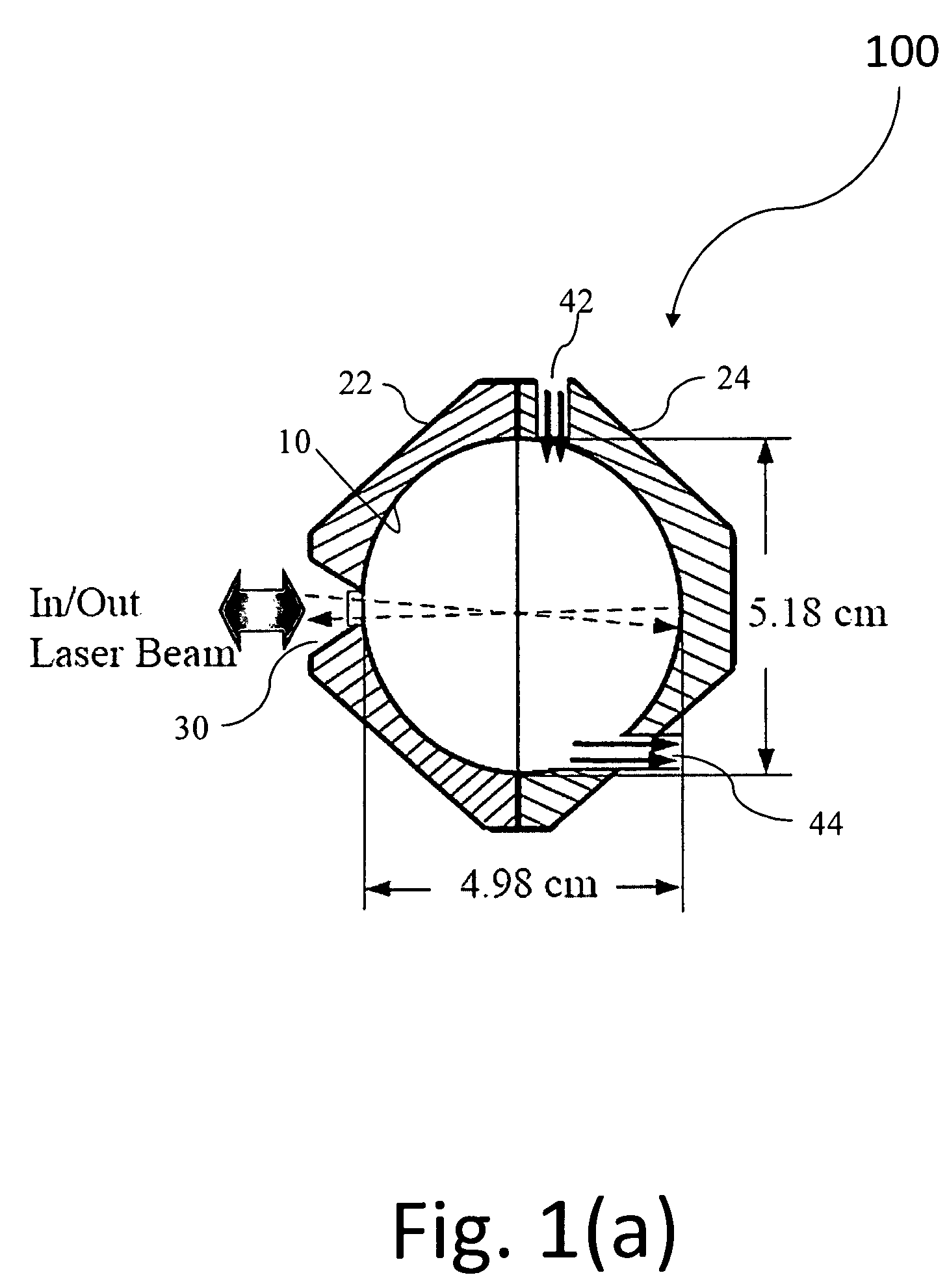
[0053]The utility of the rotationally asymmetric chaotic multi-pass cavity 100 in accordance with the present invention was demonstrated experimentally. For this first example, the chaotic multi-pass cavity 100 was fabricated from a copper substrate with R0=2.54 cm, εxy=0.01, and εyz=0.02. The cavity 100 consisted of two half shells 22, 24 shaped by a traditional milling process, which had a manufacturing accuracy of about 5.1 μm in the cavity radius. Afterwards, a Ti / Au (300 / 3000 Å) coating was deposited onto the inner polished cavity surface 10 by e-beam evaporation. Two such shells 22, 24 were manufactured and fastened to each other permanently to yield the structure illustrated in FIG. 1(a). A 2 mm diameter aperture was drilled at the front cavity shell 22 to provide the optical port 30 for light to be coupled in and out. The gas inlet and outlet ports 42, 44 were located at the top and bottom ends of the cavity 100 so that the ports 42, 44 did not interfere with the circulating...


PUM

PropertyMeasurementUnit
path lengthaaaaaaaaaa
volumeaaaaaaaaaa

Abstract

The present invention relates to a rotationally asymmetric chaotic optical multi-pass cavity useful in optical gas sensing spectroscopy, optical delay lines, and laser amplification systems, for example. The cavity may include a single closed mirror having a light reflective surface that is deformed in two orthogonal directions and more particularly, but not exclusively, in the shape of a quadrupole in both horizontal and vertical planes. The cavity includes a light entry port and a light exit port which may be the same or separate ports, as well as a gas inlet and a gas outlet. The optical path length, the beam divergence rate, and the spot pattern are controlled by selecting the cavity deformation coefficients and the input beam direction to achieve the desired beam path and beam quality.

Description

RELATED APPLICATIONS[0001]This application claims the benefit of priority of U.S. Provisional Application No. 60 / 968,450, filed on Aug. 28, 2007, the entire contents of which application is incorporated herein by reference.GOVERNMENT LICENSE RIGHTS[0002]This invention was made with government support under MIRTHE-EEC-0540832 awarded by the National Science Foundation. The government has certain rights in the invention.FIELD OF THE INVENTION[0003]The present invention relates generally to a rotationally asymmetric chaotic optical multi-pass cavity, and more particularly, but not exclusively, to a single closed reflecting surface having the shape of a quadrupole, and to the use of such cavities in optical gas sensing.BACKGROUND[0004]A multi-pass cavity or cell is an optical device, in which light bounces between mirrors a number of times in at least one stable orbit before exiting the system. A traditional multi-pass cell has a fairly complex structure that typically includes a glass ...

Claims


Application Information

Patent Timeline
Patent Type & Authority Patents(United States)
IPC IPC(8): G01N21/00H01S3/08
CPCG01J3/0254G01N21/031G02B2207/117H01S3/083B33Y80/00
Inventor QU, DONGXIAGMACHL, CLAIRE
Owner THE TRUSTEES FOR PRINCETON UNIV
Learn More