Holographic reconstruction system and method with a sequence of visibility regions

a reconstruction system and visibility region technology, applied in the field of holographic reconstruction system, can solve the problems of disappearance of visibility, difficult to find the borders of the reconstruction volume for an observer, and difficulty in detecting the visibility of the three-dimensional reconstruction

Active Publication Date: 2012-10-23
SEEREAL TECHNOLOGIES
View PDF11 Cites 1 Cited by
  • Summary
  • Abstract
  • Description
  • Claims
  • Application Information

AI Technical Summary

Benefits of technology

[0011]It is therefore the object of the present invention to provide a holographic reconstruction system which ensures that one or multiple observers can watch a reconstructed scene correctly even if they move.

Problems solved by technology

However, this may lead to problems with the visibility of the three-dimensional reconstruction, if the observer eye is only partly situated inside the visibility region.
Already a slight movement of the observer may cause effects such as disappearance of visibility, vignetting or distortion of the spatial frequency spectrum.
Moreover, the borders of the reconstruction volume are difficult to find for an observer whose eyes are situated outside the visibility region.
This causes the deflection means to move intermittently, which is difficult to be realised using conventional means, in particular at high frequencies, e.g. higher than 20 Hz, as they are easily required when realising a colour multiplexing mode or when simultaneously serving multiple observers.
Again, this is difficult to be realised using conventional means.

Method used


Image

  • Holographic reconstruction system and method with a sequence of visibility regions
  • Holographic reconstruction system and method with a sequence of visibility regions
  • Holographic reconstruction system and method with a sequence of visibility regions

Examples


first embodiment

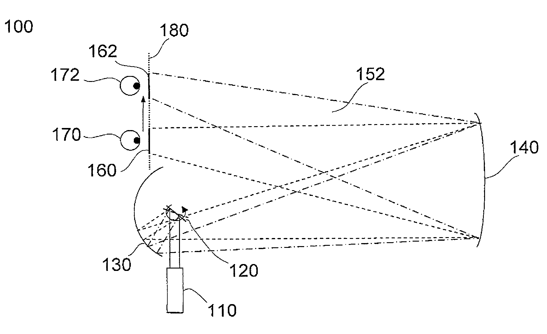
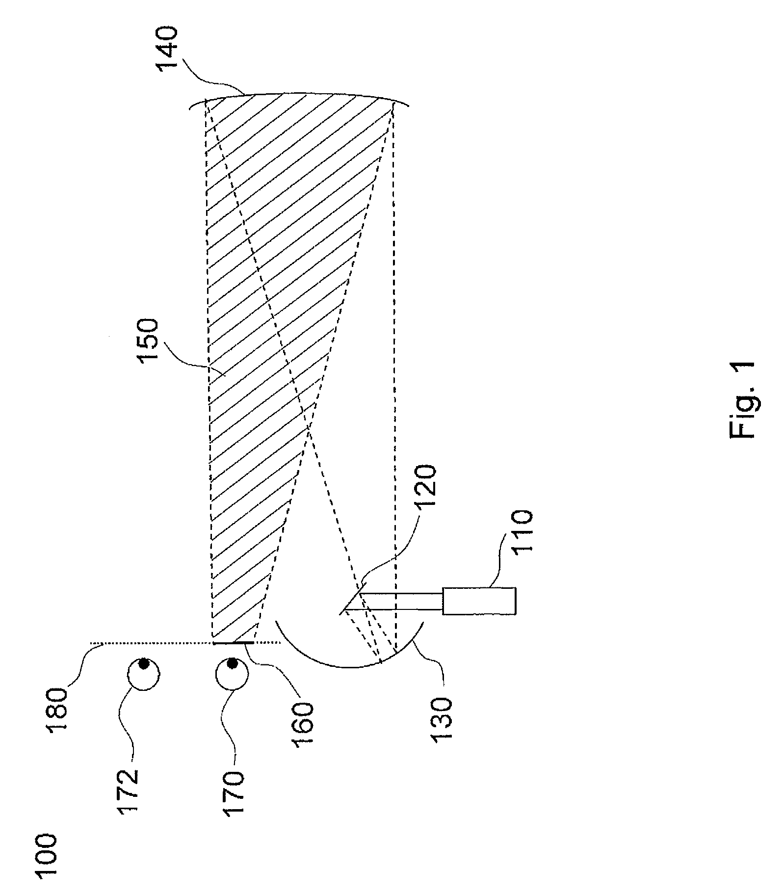
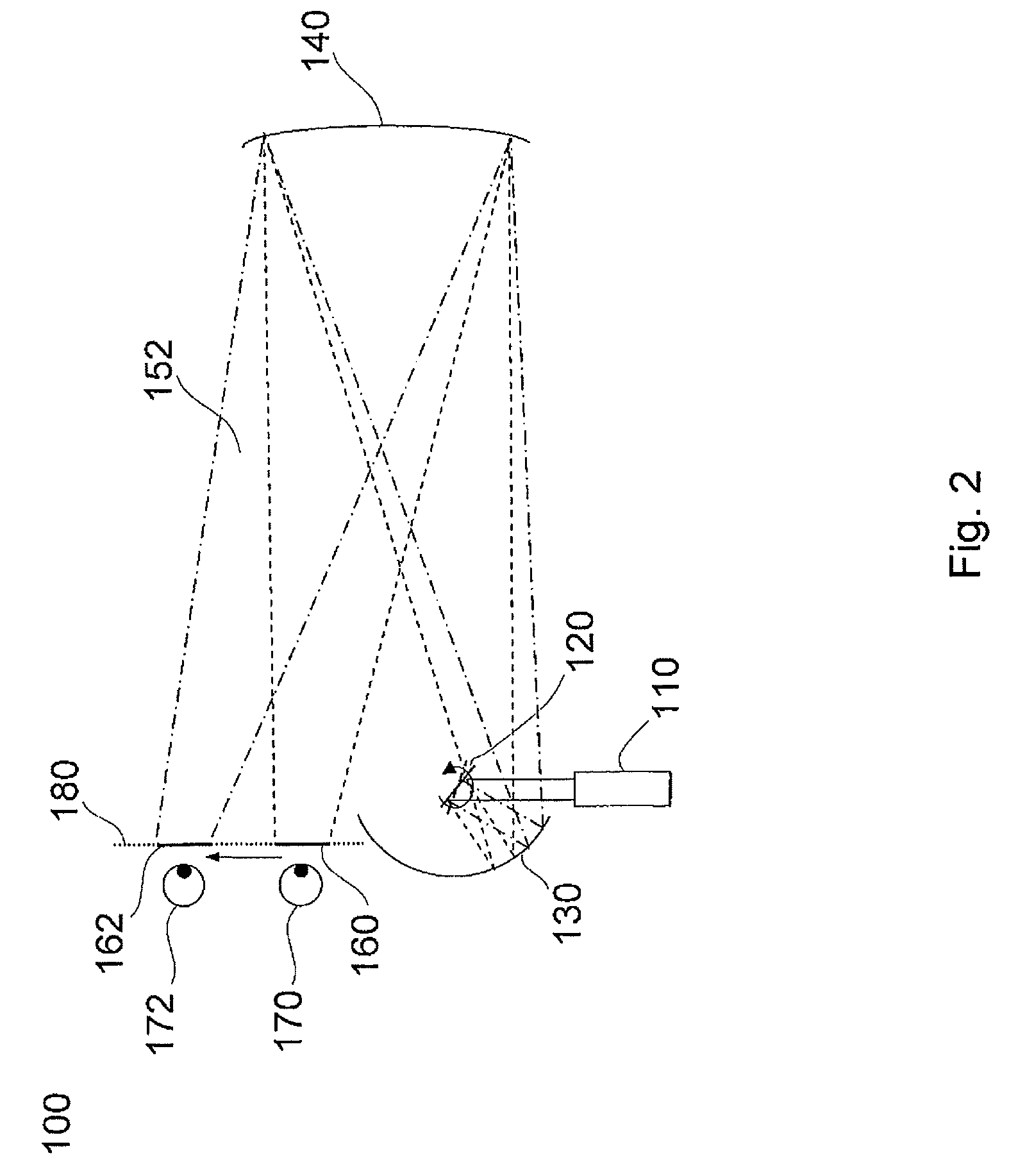
[0053]FIG. 4 is a simplified view of an inventive holographic reconstruction system 400 at a first point of time. The drawing shows light source means 410, 412, spatial light modulator means (SLM) 420, 422, a beam splitter 430, 432, a telecentric lens 440, 442, deflection means 450, 452, a projection lens 460, 462 and reflection means 470, 472. A display screen 480 is only provided once in the entire arrangement. Further, a visibility region 490, 492, and eye position 500, 502, a reconstruction volume 510, 512 and a visibility range 520, 522 are shown. Deflection control means for controlling the deflection means and light control means for generating light pulses are not explicitly shown in this drawing.

[0054]As can be seen in the drawing, the entire arrangement comprises two assemblies of analogous design. Each assembly generates the image for one eye. The following description relates to only one of those assemblies. A person skilled in the art can easily translate the principle...

second embodiment

[0070]FIG. 7 shows the general design of deflection means 700 according to this invention with an optically addressable spatial light modulator (OASLM) 712 with a diffractive structure and a deflection mirror 714, which is attached to the OASLM 712.

[0071]According to this embodiment, the OASLM 712 comprises a first glass plate 716 with a transparent electrode, an LC layer 718, which forms the diffractive structure of the OASLM 712 and which contains LC molecules, a transparent, photosensitive semiconductor layer 720, and a second glass plate 722 as the substrate. In this embodiment, the OASLM 712 is transparent for the light which is used for the reconstruction of the three-dimensional scene, so that this light can reach the deflection mirror 714 which is arranged behind.

third embodiment

[0072]FIG. 8 shows the general design of deflection means 800 according to this invention with an optically addressable spatial light modulator (OASLM) 812 with a diffractive structure, where a deflection mirror 814 in the form of a reflecting layer is integrated into the OASLM 812.

[0073]In this embodiment, the OASLM 812 again comprises a glass plate 816 with a transparent electrode, an LC layer 818, which forms the diffractive structure of the OASLM 13 and which contains LC molecules, a photosensitive semiconductor layer 820, and a glass plate 822 as the substrate. The deflection mirror 814 is integrated between the LC layer 818 and the semiconductor layer 820 in this embodiment.

[0074]Alternatively, it is possible that the OASLM 712, 812 exhibits a refractive structure or a combination of a diffractive and a refractive structure, so that also a refractive light modulation is possible on the OASLM with a refractive index variation.

[0075]It is further possible that the deflection mir...


PUM


Abstract

A holographic reconstruction system and method for the three-dimensional reconstruction of object light points of a scene. The system includes spatial light modulation means which modulate light waves capable of interference with at least one video hologram, focusing means which focus the modulated light waves so that a viewer can view the reconstructed object light points of the scene from a visibility region that is thereby produced by focusing, and deflection means which position the visibility region by aligning the modulated light waves. The holographic reconstruction system includes deflection control means for controlling the deflection means to sequentially adjust the visibility region to different contiguous viewing positions, and light controlling means for switching the light waves in synchronicity with the deflection control means.

Description

CROSS REFERENCE TO RELATED APPLICATIONS[0001]This application claims the priority of PCT / EP2008 / 055894, filed on May 4, 2008, which claims priority to German Application No. 10 2007 024235.4, filed May 21, 2007, the entire contents of which are hereby incorporated in total by reference.BACKGROUND OF THE INVENTION[0002]The present invention relates to a holographic reconstruction system for the three-dimensional reconstruction of object light points of a scene, and to an according method. The holographic reconstruction system comprises spatial light modulator means which modulate light waves which are capable of generating interference with at least one video hologram, focussing means which focus the modulated light waves such that an observer can watch the reconstructed object light points of the scene from a visibility region which is thus generated by way of focussing, and deflection means which position the visibility region by way of directing the modulated light waves.[0003]In ...

Claims


Application Information

Patent Timeline
Patent Type & Authority Patents(United States)
IPC IPC(8): G02B5/32G03H1/30G03H1/02G03H1/08
CPCG03H1/2205G03H1/2294G03H2226/05G03H2001/2292G03H2223/24G03H2001/2242G03H2001/221G03H2001/2239
Inventor BUSCHBECK, STEFFENSCHWERDTNER, ARMIN
Owner SEEREAL TECHNOLOGIES
Why Eureka
Try Eureka