Printed circuit board fastening structure

a technology of printed circuit board and fastening structure, which is applied in the direction of supporting structure mounting, electrical apparatus construction details, casings/cabinets/drawers, etc., can solve the problems of occupying a large space above the printed circuit board, tedious and time-consuming installation of printed circuit board close to the casing, and circuit elements on the printed circuit board are even more crowded, so as to facilitate manual installation of printed circuit board, reduce cost, and save installation time

Active Publication Date: 2012-10-23
SPI ELECTRONICS +1
View PDF18 Cites 5 Cited by
  • Summary
  • Abstract
  • Description
  • Claims
  • Application Information

AI Technical Summary

Benefits of technology

[0007]Therefore, the primary object of the present invention is to provide a printed circuit board fastening structure that can reduce cost and save installation time to facilitate manual installation of the printed circuit board to overcome the disadvantages of the conventional techniques.
[0008]The printed circuit board fastening structure according to the invention has a printed circuit board formed with a first bearing surface abutting a casing and a second bearing surface. The first bearing surface is coupled with at least one support member which has at least one leg connecting to the first bearing surface and an end portion with a fastening hole formed thereon. The end portion is adjacent to the casing. A fastening element is provided to run through the casing from another side to couple with the anchor hole. Hence fastening can be done by running the fastening element through the casing from the outer side thereof to couple with the support member, then the printed circuit board can be anchored on the casing. The invention mainly aims to fasten the printed circuit board of electronic devices. The electronic devices may be power supply. The casing may be a housing of a power supply. Through the invention, operators can fasten the printed circuit board at one side (namely the outer side of the casing) where more space is available. It eliminates the problem of the conventional techniques that do installation in a smaller space inside the casing. Moreover, the support member is connected to the first bearing surface without occupying the second bearing surface of the printed circuit board, hence the second bearing surface has a sufficient area to accommodate circuit elements or facilitate heat dissipation.
[0011]2. Installation is performed on a roomier side of the printed circuit board, thus is easier.
[0012]3. More space can be saved on the second bearing surface to accommodate more circuit elements or facilitate heat dissipation.

Problems solved by technology

As the space between the printed circuit board and the casing usually is limited, installing the printed circuit board close to the casing is a tedious and time-consuming task.
However, the bolt takes substantial space above the printed circuit board.
Thus the circuit elements on the printed circuit board are even more crowded.
Hence it does not provide much improvement on printed circuit board fastening operation.
But wedging the printed circuit board in the annular groove of the spherical coupling element is troublesome.
In the event that there is a fabrication error on the spherical coupling elements and the anchor holes, coupling them is even more difficult.
All these create a lot of problems for manual installation.
Such an approach requires forming the notches on the printed circuit board at a greater size, and results in wasting of the precious area of the printed circuit board.
Hence it also has the drawbacks of wasting space and higher cost.
They all have the problems mentioned above, such as occupying more space, higher costs, and difficult installation from the inner side to the outer side.

Method used


Image

  • Printed circuit board fastening structure
  • Printed circuit board fastening structure
  • Printed circuit board fastening structure

Examples


Embodiment Construction

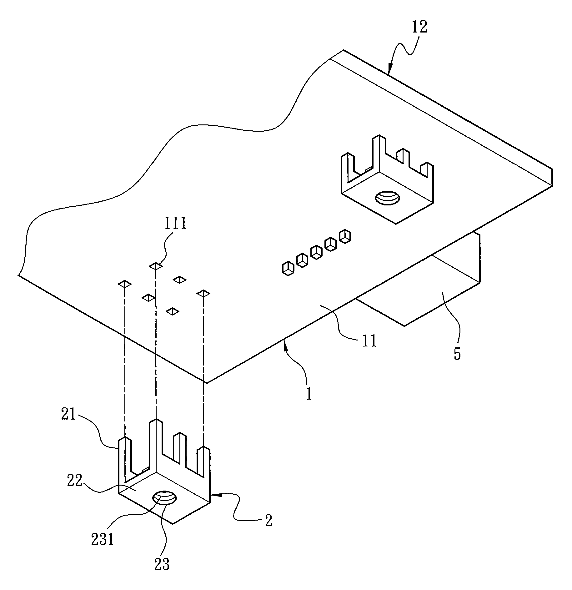
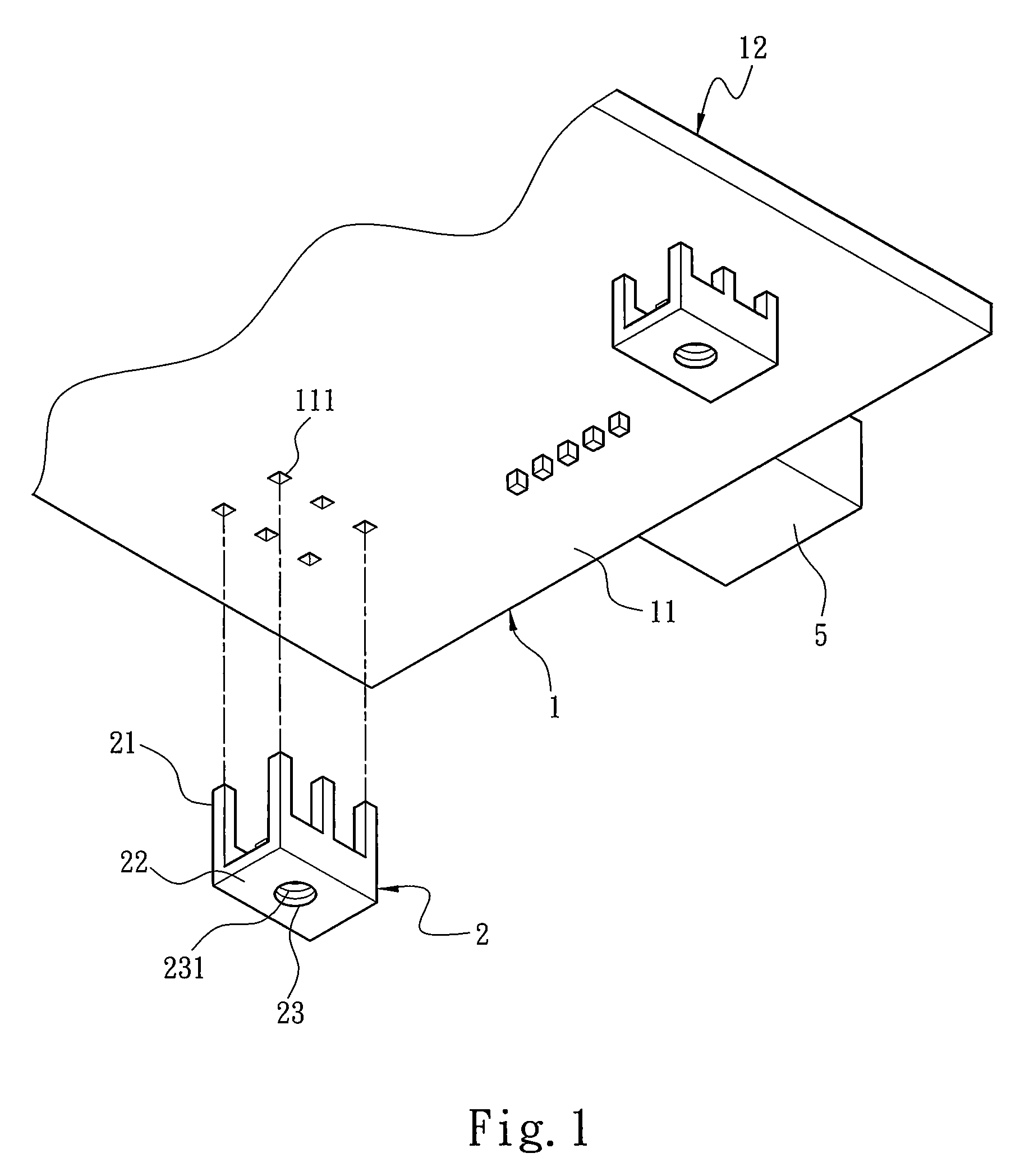
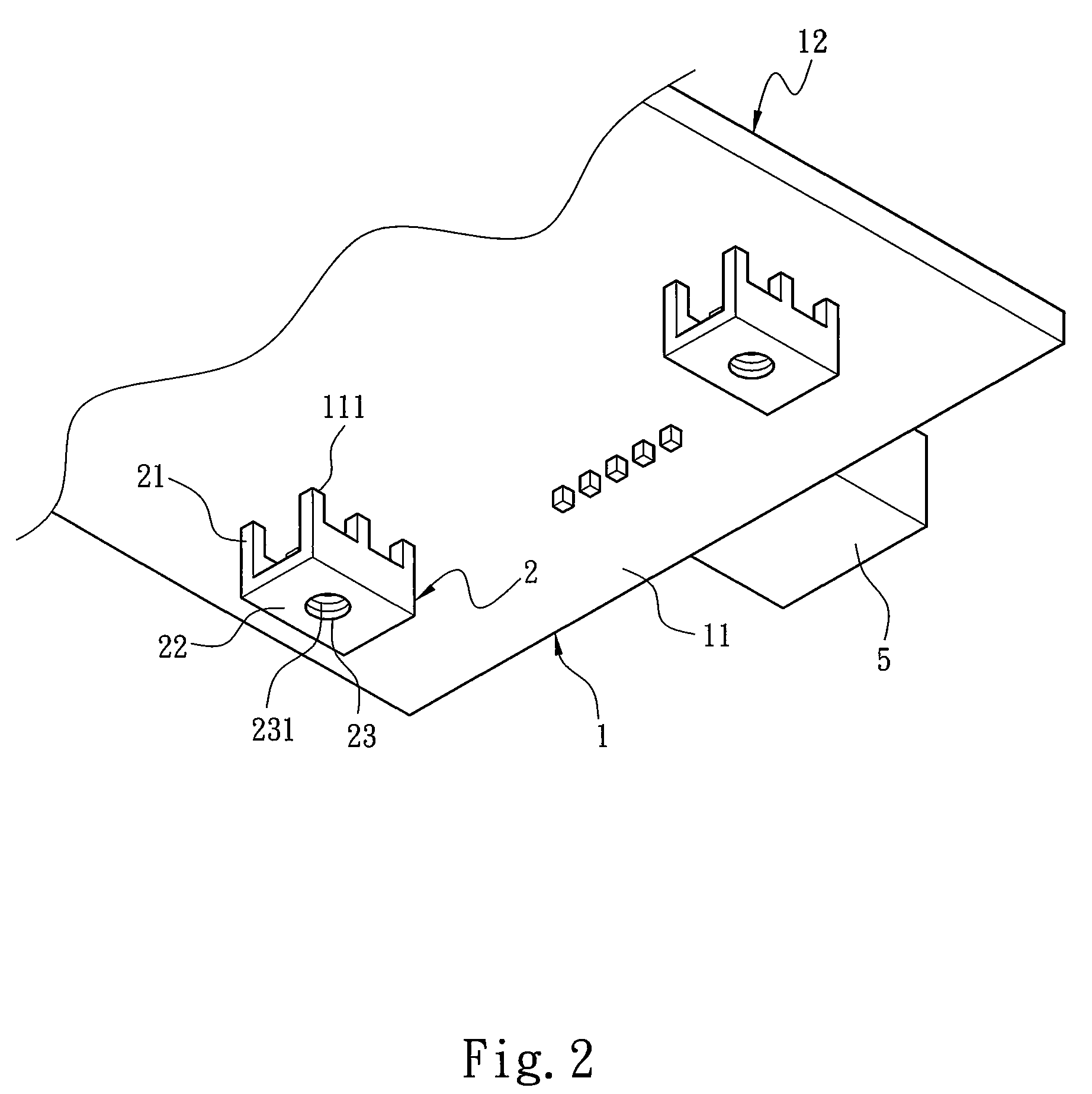
[0018]The present invention aims to provide a printed circuit board fastening structure. Please refer to FIG. 1, a printed circuit board 1 and at least one support member 2 are provided. The printed circuit board 1 has a first bearing surface 11 abutting a casing 3 (also referring to FIG. 3) of an electronic device and a second bearing surface 12. There is a larger space above the second bearing surface 12, hence a plurality of bulkier circuit elements 5 (an input port is shown in the drawings as an example) such as input ports, transformers, capacitors, integrated circuits, heat sinks and the like can be installed on the second bearing surface 12. The first bearing surface 11 is located on another side opposite to the second bearing surface 12. Although the first bearing surface 11 is closer to the casing 3 and results in a smaller space, other smaller circuit elements 5 (such as integrated circuits, semiconductor elements and the like) still can be installed thereon. The first bea...


PUM


Abstract

A printed circuit board fastening structure aims to fasten a printed circuit board which has a first bearing surface abutting and coupling on a casing and a second bearing surface. The first bearing surface is coupled with at least one support member. The support member has at least one leg connecting to the first bearing surface and an end portion formed with a fastening hole. The end portion is adjacent to the casing. A fastening element is provided to run through the casing from another side thereof to couple with the support member, thereby to fasten the printed circuit board to the casing.

Description

FIELD OF THE INVENTION[0001]The present invention relates to a printed circuit board fastening structure for fastening a printed circuit board to a casing of an electronic device through at least one fastening element.BACKGROUND OF THE INVENTION[0002]A conventional power supply ought to have a bigger transformer, more capacitors and larger switches to provide a greater amount of current and power. To meet safety requirements, the circuit elements also have to be spaced from each other at a desired insulation distance, and provide sufficient space to disperse heat. All these make the printed circuit board holding the aforesaid circuit elements to be installed close to the casing of the power supply to better utilize the space while still maintain a safety distance from the casing. As the space between the printed circuit board and the casing usually is limited, installing the printed circuit board close to the casing is a tedious and time-consuming task.[0003]To remedy the aforesaid ...

Claims


Application Information

Patent Timeline
Patent Type & Authority Patents(United States)
IPC IPC(8): H05K5/00
CPCH05K7/1417H05K3/3447
Inventor LU, SHAO-FENG
Owner SPI ELECTRONICS
Why Eureka
Try Eureka