System and method for vitally determining position and position uncertainty of a railroad vehicle employing diverse sensors including a global positioning system sensor

a global positioning system and sensor technology, applied in traffic control systems, navigation instruments, instruments, etc., can solve the problems of difficult demonstration of vitality claims for position systems based on kalman filtering technique, considerable preparation and careful installation of ertms systems, etc., and achieve the effect of vital determination of railroad vehicle position

Active Publication Date: 2012-10-23
ANSALDO STS USA INC
View PDF64 Cites 46 Cited by
  • Summary
  • Abstract
  • Description
  • Claims
  • Application Information

AI Technical Summary

Benefits of technology

[0022]This need and others are met by embodiments of the invention, which provide an apparatus and method for vitally determining railroad vehicle position and uncertainty employing, for example, differential GPS position reports, which are cross-checked against a track map, and also employing plural diverse sensors, such as, for example, tachometers and accelerometers. The resulting railroad vehicle position information is sufficiently reliable for use in vital applications (e.g., without limitation, vital Automatic Train Protection or Automatic Train Operation (ATP / ATO) functions, such as vital braking applications).

Problems solved by technology

The ERTMS system has been observed to require considerable preparation and careful installation.
For example, in a radar application, where one is interested in tracking a target, information about the location, speed and acceleration of the target is measured with a great deal of corruption by noise at any instant of time.
Train dynamics, while well understood and predicable in controlled circumstances are notoriously variable in actual operation, due largely to the variability of the loads applied.
Thus, claims of vitality for position systems that rely on the Kalman filtering technique are believed to be difficult to demonstrate.
The three navigation solutions are optimally blended with the external GPS / DGPS receiver and the tachometer data, and the solution is subjected to motion constraints reflecting the physical limitations of how a locomotive can move.

Method used


Image

  • System and method for vitally determining position and position uncertainty of a railroad vehicle employing diverse sensors including a global positioning system sensor
  • System and method for vitally determining position and position uncertainty of a railroad vehicle employing diverse sensors including a global positioning system sensor
  • System and method for vitally determining position and position uncertainty of a railroad vehicle employing diverse sensors including a global positioning system sensor

Examples


example 1

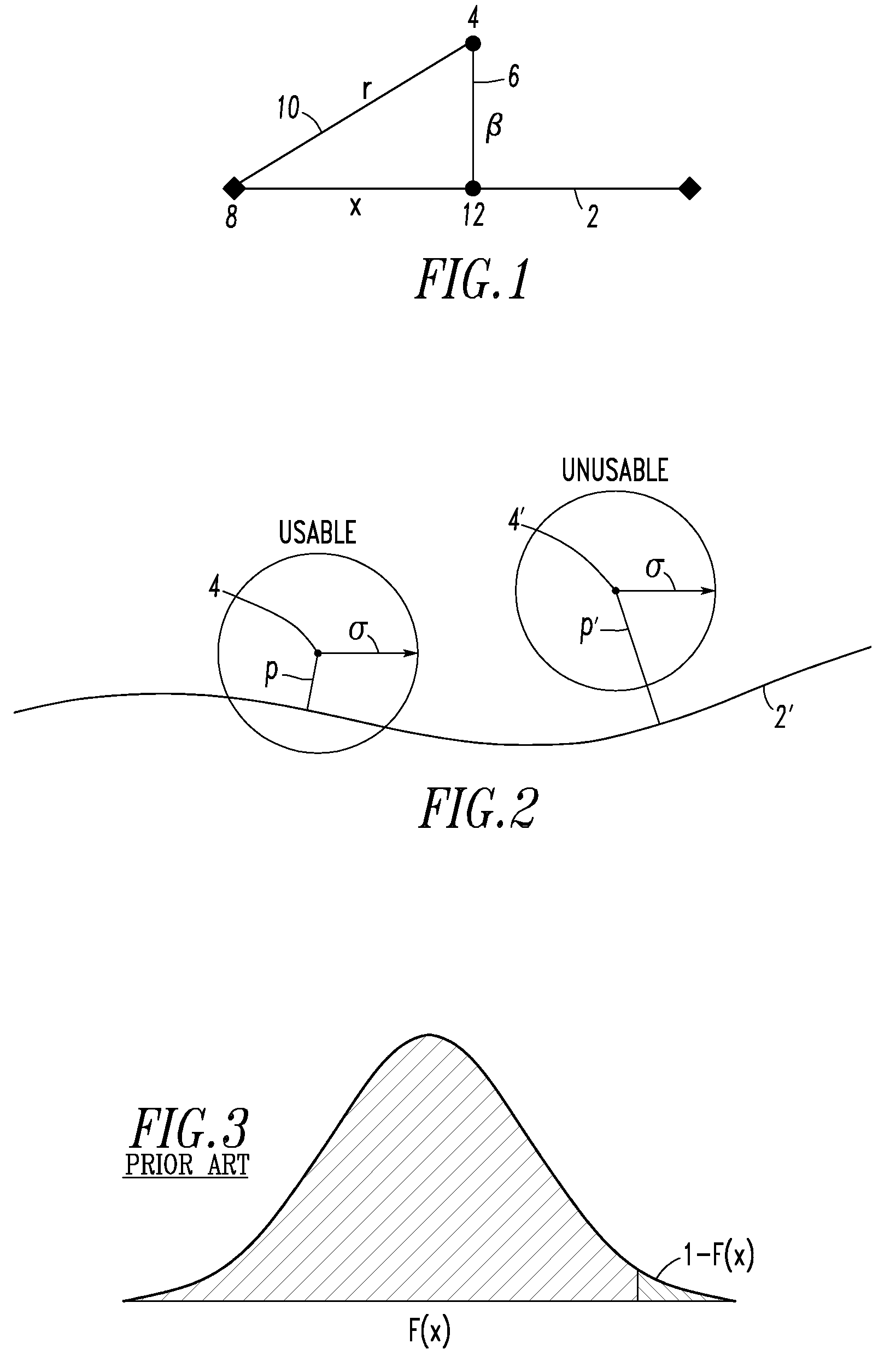
[0085]DGPS σ (commonly known as the User Equivalent Range Error (UERE)) is determined in part from Differential Lock and Horizontal Dilution of Precision (HDOP) values reported by the DGPS unit 100 and is presumed to be on the order of about 1.6 meters (5 feet). HDOP depends on the relative geometric positioning of the satellites in view (higher values of HDOP indicate relative positions that give less accurate readings). For GPS without differential correction, GPS σ is presumed to be on the order of about 5.3 meters (18 feet), such that 6σ under GPS, without differential correction, is still only about 32 meters (108 feet), which is sufficiently small for railway applications. DGPS σ is smaller because the locations of ground-based reference stations, which are known, are used to correct for atmospheric distortion, ephemeris error, and satellite / receiver clock error. The actual UERE is tracked by the GPS Support Center of the Air Force, currently known as GPSOC. As new satellites ...

example 2

[0093]The DGPS error propagation routine 50 may employ, for example, GPS reported Differential Lock and HDOP to calculate UERE. The UERE calculation is based on the observation that GPS without differential lock has a normal standard deviation of about 5.3 meters. Adding a differential GPS base unit signal will reduce the ULERE value to about 1.6 meters. Additionally, the grouping of the GPS satellites (not shown) used in the measurement has an effect, which is measured by the HDOP. For example, tightly clustered satellites lead to a relatively large HDOP, while more widely scattered satellites lead to a relatively lower HDOP.

[0094]HDOP is defined such that UERE=HDOP*√{square root over (URE2+UEE2)}, wherein UEE is User Equipment Errors (e.g., receiver noise; antenna orientation; EMI / RFI), which can be reduced to an insignificant value with appropriate equipment design, and URE is the User Range Error, which is due to atmospheric effects (e.g., propagation through the ionosphere), or...

example 3

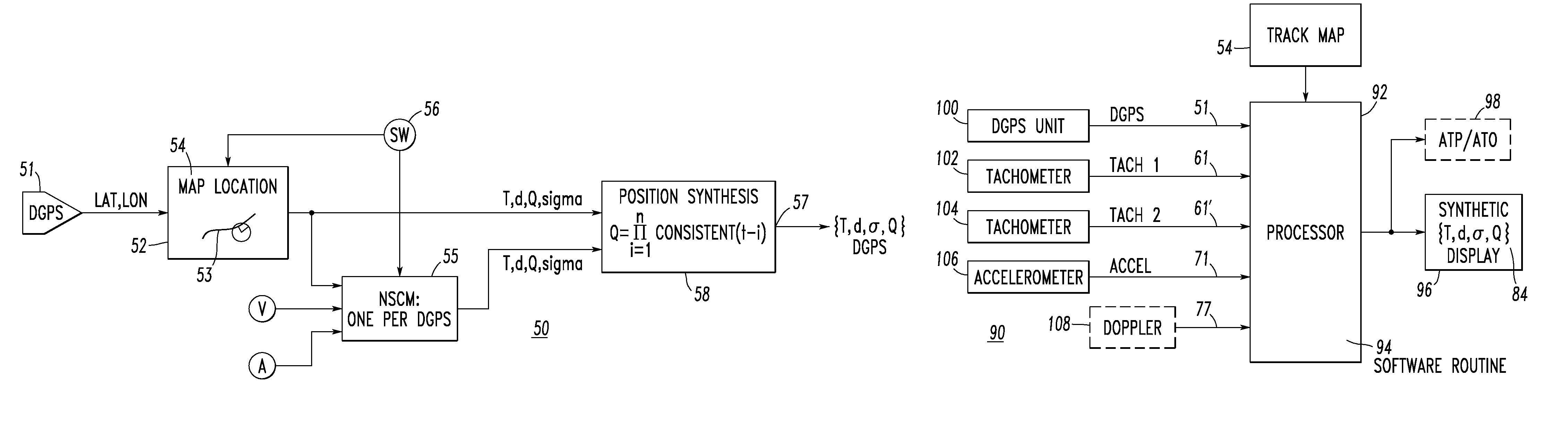
[0105]The DGPS error propagation routine 50 can employ a routine to verify DGPS veracity. In addition to selecting a suitable UERE value (e.g., Example 2, above), the system 90 preferably determines whether the DGPS unit 100 (FIG. 9) is accurately reporting differential lock and HDOP. The method is similar to Example 2, except that each sample offset is compared to the particular UERE implied by the differential lock and HDOP reported with that sample, instead of a presupposed UERE (the URE value is known, and is constant). Thus, the proportion computed is a measure of whether the DGPS unit 100 is accurately reporting differential lock and HDOP. If the value for z lies within the acceptable range of z values, which depends on the chosen level for statistical significance (e.g., 5%), then the hypothesis that the DGPS unit 100 can be believed is accepted.


PUM


Abstract

A system vitally determines a position of a train. The system includes a plurality of diverse sensors, such as tachometers and accelerometers, structured to repetitively sense at least change in position and acceleration of the train, a global positioning system sensor, which is diverse from each of the diverse sensors, structured to repetitively sense position of the train, and a track map including a plurality of track segments which may be occupied by the train. A processor cooperates with the diverse sensors, the global positioning system sensor and the track map. The processor includes a routine structured to provide measurement uncertainty for each of the diverse sensors and the global positioning system sensor. The routine cross-checks measurements for the diverse sensors, and cross-checks the global positioning system sensor against the track map. The routine provides the vitally determined position of the train and the uncertainty of the vitally determined position.

Description

BACKGROUND OF THE INVENTION[0001]1. Field of the Invention[0002]This invention pertains generally to systems for monitoring railroad vehicles and, more particularly, to such systems for determining the position of a train. The invention also pertains to methods for determining the position of a railroad vehicle.[0003]2. Background Information[0004]In the art of railway signaling, traffic flow through signaled territory is typically directed by various signal aspects appearing on wayside indicators or cab signal units located on board railway vehicles. The vehicle operators recognize each such aspect as indicating a particular operating condition allowed at that time. Typical practice is for the aspects to indicate prevailing speed conditions.[0005]For operation of this signaling scheme, a track is typically divided into cascaded sections known as “blocks.” These blocks, which may be generally as long as about two to about five miles, are electrically isolated from adjacent blocks by...

Claims


Application Information

Patent Timeline
Patent Type & Authority Patents(United States)
IPC IPC(8): G01C21/10
CPCB61L25/025B61L25/026G01C21/165B61L2205/04
Inventor HAYNIE, MICHAEL B.LAURUNE, WILLIAM R.
Owner ANSALDO STS USA INC
Why Eureka
Try Eureka