
Implementing spare latch placement quality determination

a technology of quality determination and spare latch, applied in the field of data processing, can solve the problems of reducing the usefulness of spare latches, no known good solution to problems, and practically impossible to make effective use of spare latches, and achieve the effect of not having negative effects

Active Publication Date: 2012-10-23
GLOBALFOUNDRIES U S INC
View PDF6 Cites 2 Cited by
  • Summary
  • Abstract
  • Description
  • Claims
  • Application Information

AI Technical Summary

Benefits of technology

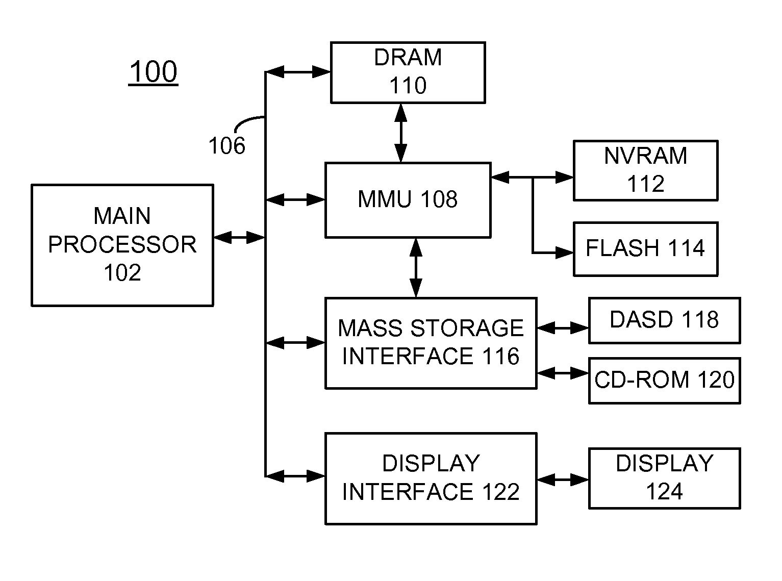
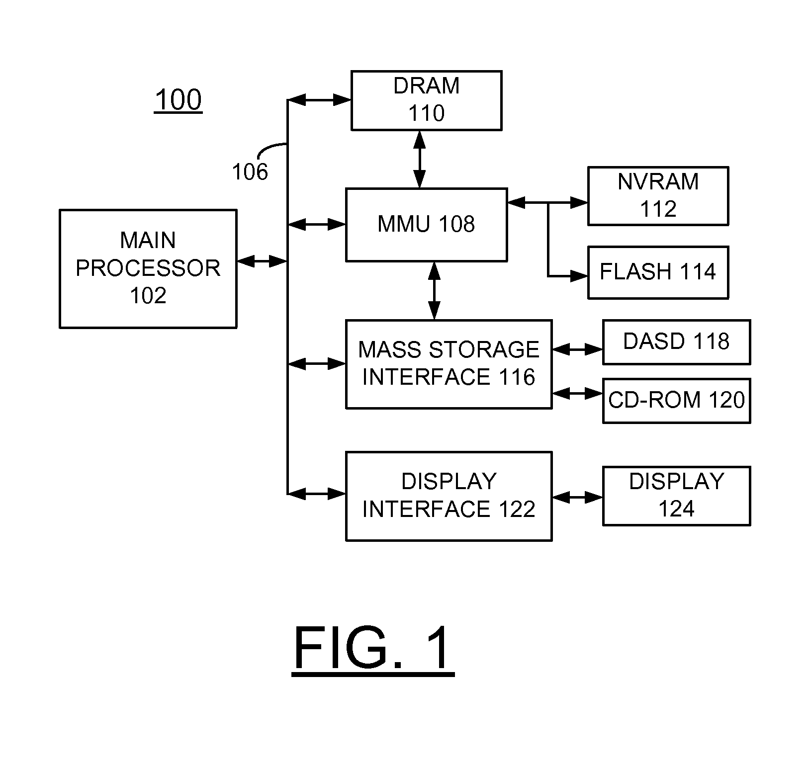
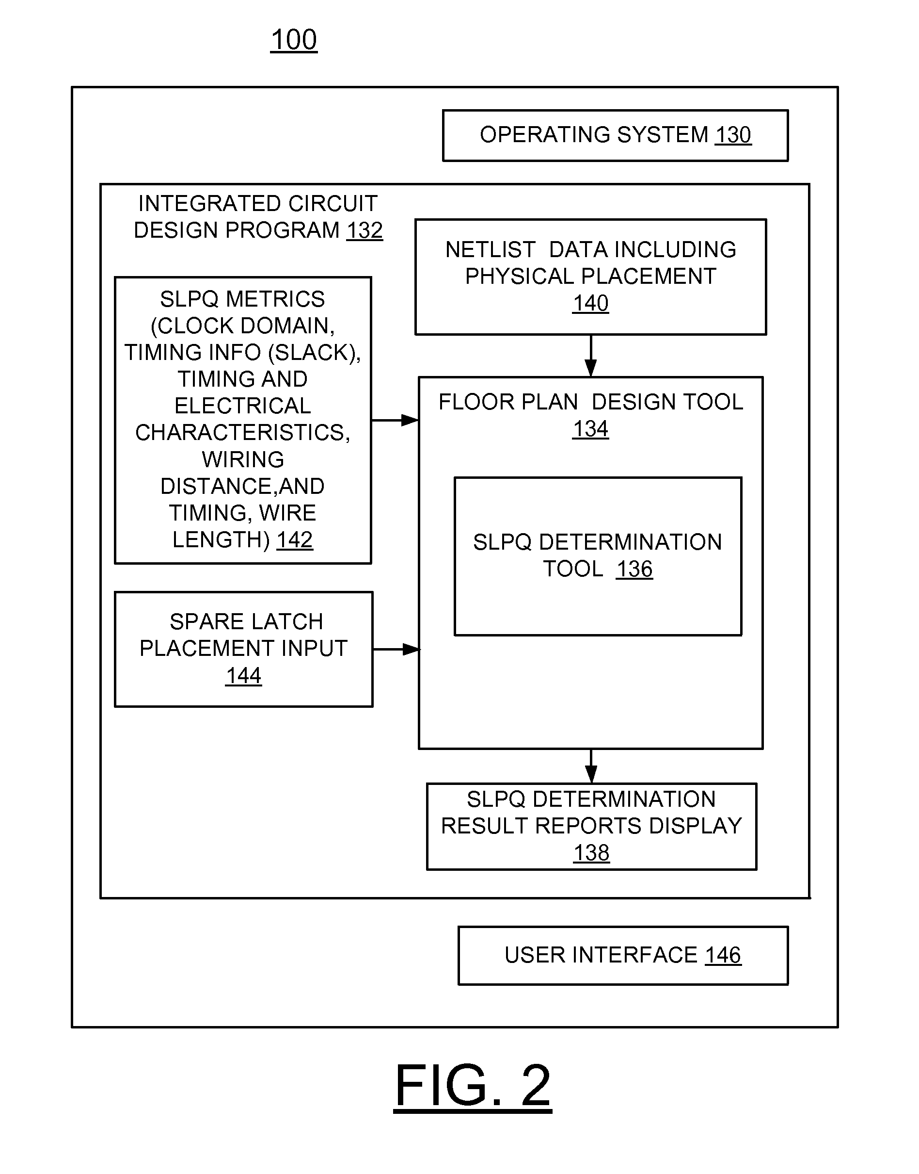
[0007]A principal aspect of the present invention is to provide a method, system and computer program product for implementing spare latch placement quality (SLPQ) determination in a floor plan design of an integrated circuit chip. Other important aspects of the present invention are to provide such method, system, and computer program product substantially without negative effects and that overcome many of the disadvantages of prior art arrangements.
[0009]In accordance with features of the invention, the SLPQ metric is used to quickly determine the quality of spare latch placement in a hardware design.
[0011]In accordance with features of the invention, an algorithm could be applied in continued floor plan processing which uses the newly defined SLPQ metric as an optimization target to improve the quality of spare latch placement.

Problems solved by technology

This poses a problem for larger or more complex designs since the final physical location of the spare latches may seriously reduce their helpfulness in implementing ECOs.
It may be practically impossible to make effective use of these spares due to timing, wiring, or other constraints.
Currently there are no known good solutions to the problem of determining and communicating the quality of spare latch placement.
The simple method of showing the location of all spare latches does not provide enough information for the hardware designer to make an informed decision about the quality of the placement.
For example, all spares may exist in the upper-left of the floor plan design, but perhaps that is the best location or maybe it is the worst, there is not enough information in a simple visualization of spare latch placement.

Method used


Image

  • Implementing spare latch placement quality determination
  • Implementing spare latch placement quality determination
  • Implementing spare latch placement quality determination

Examples


Embodiment Construction

[0018]In the following detailed description of embodiments of the invention, reference is made to the accompanying drawings, which illustrate example embodiments by which the invention may be practiced. It is to be understood that other embodiments may be utilized and structural changes may be made without departing from the scope of the invention.

[0019]The terminology used herein is for the purpose of describing particular embodiments only and is not intended to be limiting of the invention. As used herein, the singular forms “a”, “an” and “the” are intended to include the plural forms as well, unless the context clearly indicates otherwise. It will be further understood that the terms “comprises” and / or “comprising,” when used in this specification, specify the presence of stated features, integers, steps, operations, elements, and / or components, but do not preclude the presence or addition of one or more other features, integers, steps, operations, elements, components, and / or gr...


PUM


Abstract

A method, system and computer program product are provided for implementing spare latch placement quality (SLPQ) determination in a floor plan design of an integrated circuit chip. A spare latch placement quality (SLPQ) metric data function is defined and compared to a spare latch placement input with a series of calculations performed. The spare latch placement quality (SLPQ) determination is made based upon the compared SLPQ metric data function and the spare latch placement input. Then associated reports including textual and visual reports are generated responsive to the SLPQ determination. In addition, a new spare latch placement can be constructed with an algorithm responsive to the SLPQ determination.

Description

FIELD OF THE INVENTION[0001]The present invention relates generally to the data processing field, and more particularly, relates to a method, system and computer program product for implementing spare latch placement quality (SLPQ) determination in a floor plan design of an integrated circuit chip.DESCRIPTION OF THE RELATED ART[0002]In integrated circuit design, such as microprocessor hardware design, it is typical to include unused latching elements which can be utilized in the event of an engineering change order (ECO). These latches are typically referred to as spares since they reside in the design, but are not actually used functionally. From a timing, physical design, and test perspective these spare latches appear similar to latches which are used. The number of spare latches is generally proportional to the robustness of the hardware design. In other words, a new design has a greater chance of late ECOs and therefore more spares are recommended.[0003]Once the spares are inse...

Claims


Application Information

Patent Timeline
Patent Type & Authority Patents(United States)
IPC IPC(8): G06F17/50G06F9/455
CPCG06F17/5072G06F2217/72G06F2117/06G06F30/392
Inventor AMUNDSON, MICHAEL DAVIDDARSOW, CRAIG MARSHALLNELSON, ELDON GALERICKERT, DENNIS MARTIN
Owner GLOBALFOUNDRIES U S INC
Learn More