
Implementing enhanced optical mirror coupling and alignment utilizing two-photon resist

a technology of optical mirror and two-photon resist, applied in the field of data processing, can solve the problems of etching and mechanical ablation, unable to achieve the effect of optical transparency, affecting the quality of optical mirrors, and requiring high-efficiency manufacturing

Inactive Publication Date: 2015-03-03
INT BUSINESS MASCH CORP
View PDF27 Cites 8 Cited by
  • Summary
  • Abstract
  • Description
  • Claims
  • Application Information

AI Technical Summary

Benefits of technology

This patent describes a new method and system for coupling optical mirrors using a special circuit board design. This method allows for more precise alignment and optical coupling, resulting in better optical power transfer. The system is efficient, effective, and repeatable across different circuit boards. Overall, this invention provides a more optically transparent and accurate way to couple optical mirrors.

Problems solved by technology

One of the difficult steps to utilize an optical interface is to align the optical channel from the driving IC package into the PCB, requiring a change from the vertical to horizontal plane.
The processes by which this is presently accomplished include etching and mechanical ablation, both of which are relatively inaccurate, time consuming and expensive relative to conventional card manufacturing processes.

Method used


Image

  • Implementing enhanced optical mirror coupling and alignment utilizing two-photon resist
  • Implementing enhanced optical mirror coupling and alignment utilizing two-photon resist
  • Implementing enhanced optical mirror coupling and alignment utilizing two-photon resist

Examples


Embodiment Construction

[0014]In the following detailed description of embodiments of the invention, reference is made to the accompanying drawings, which illustrate example embodiments by which the invention may be practiced. It is to be understood that other embodiments may be utilized and structural changes may be made without departing from the scope of the invention.

[0015]The terminology used herein is for the purpose of describing particular embodiments only and is not intended to be limiting of the invention. As used herein, the singular forms “a”, “an” and “the” are intended to include the plural forms as well, unless the context clearly indicates otherwise. It will be further understood that the terms “comprises” and / or “comprising,” when used in this specification, specify the presence of stated features, integers, steps, operations, elements, and / or components, but do not preclude the presence or addition of one or more other features, integers, steps, operations, elements, components, and / or gr...


PUM

PropertyMeasurementUnit
depthsaaaaaaaaaa
reflectionaaaaaaaaaa
electrically conductiveaaaaaaaaaa

Abstract

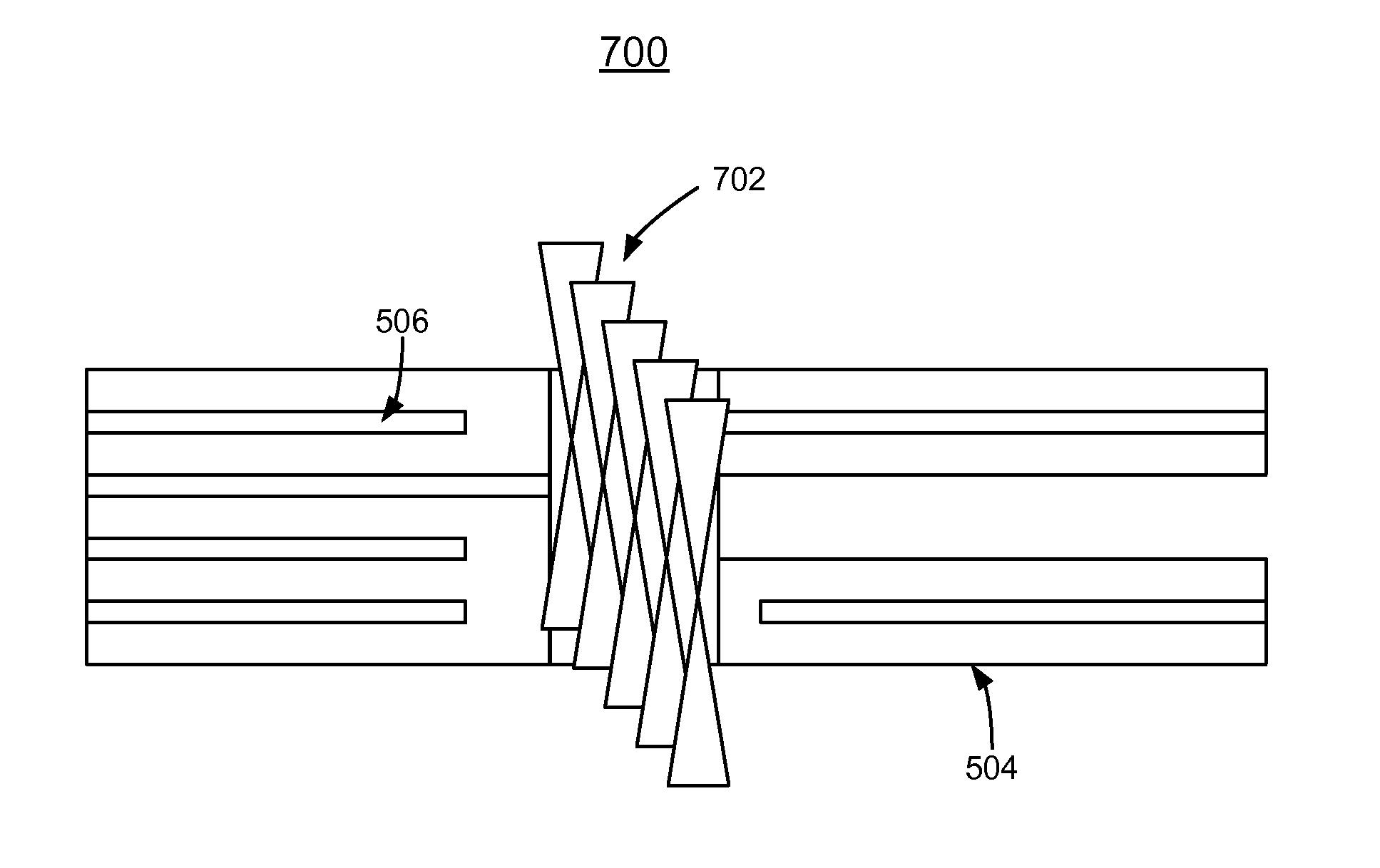
A method, system and computer program product for implementing an enhanced optical mirror coupling and alignment mechanism utilizing two-photon resist. An initial placement is provided for one or more vias on a printed circuit board. A via is filled with a resist. A series of tightly focused light beams suitably exposes the resist at varying depths in the via, the varying depths defining a sloped polymer in the via after removing resist that had not been at the focus of the light beam. The sloped polymer is coated with reflective material to reflect light into or out of the via.

Description

FIELD OF THE INVENTION[0001]The present invention relates generally to the data processing field, and more particularly, relates to a method, system and computer program product for implementing an enhanced optical mirror coupling and alignment utilizing two-photon resist.DESCRIPTION OF THE RELATED ART[0002]As used in the following specification and claims, the term printed circuit board (PCB) should be broadly understood to include circuit cards, circuit boards, circuit wiring boards, and various other three-dimensional electronic packages including but not limited to first level packages.[0003]Circuits fabricated on printed circuit boards frequently consist of multiple electrical traces distributed over multiple layers, or planes, of the printed circuit board (PCB). Electrical traces on different planes of the PCB may be electrically connected with a plated through hole, or plated via. A via is a hole in a PCB that may be plated with electrically conductive material on its sides s...

Claims


Application Information

Patent Timeline
Patent Type & Authority Patents(United States)
IPC IPC(8): G02B6/26B05D5/06G02B6/34
CPCB05D5/063G02B6/34B05C9/08B05C11/00G02B6/00H05K1/0274H05K2201/09063H05K2201/09827H05K2201/2054H05K2203/107
Inventor ATTA, EMMANUELBERGER, DARCYDANGLER, JOHN R.DOYLE, MATTHEW S.HEFNER, JESSELIANG, THOMAS W.
Owner INT BUSINESS MASCH CORP
Learn More